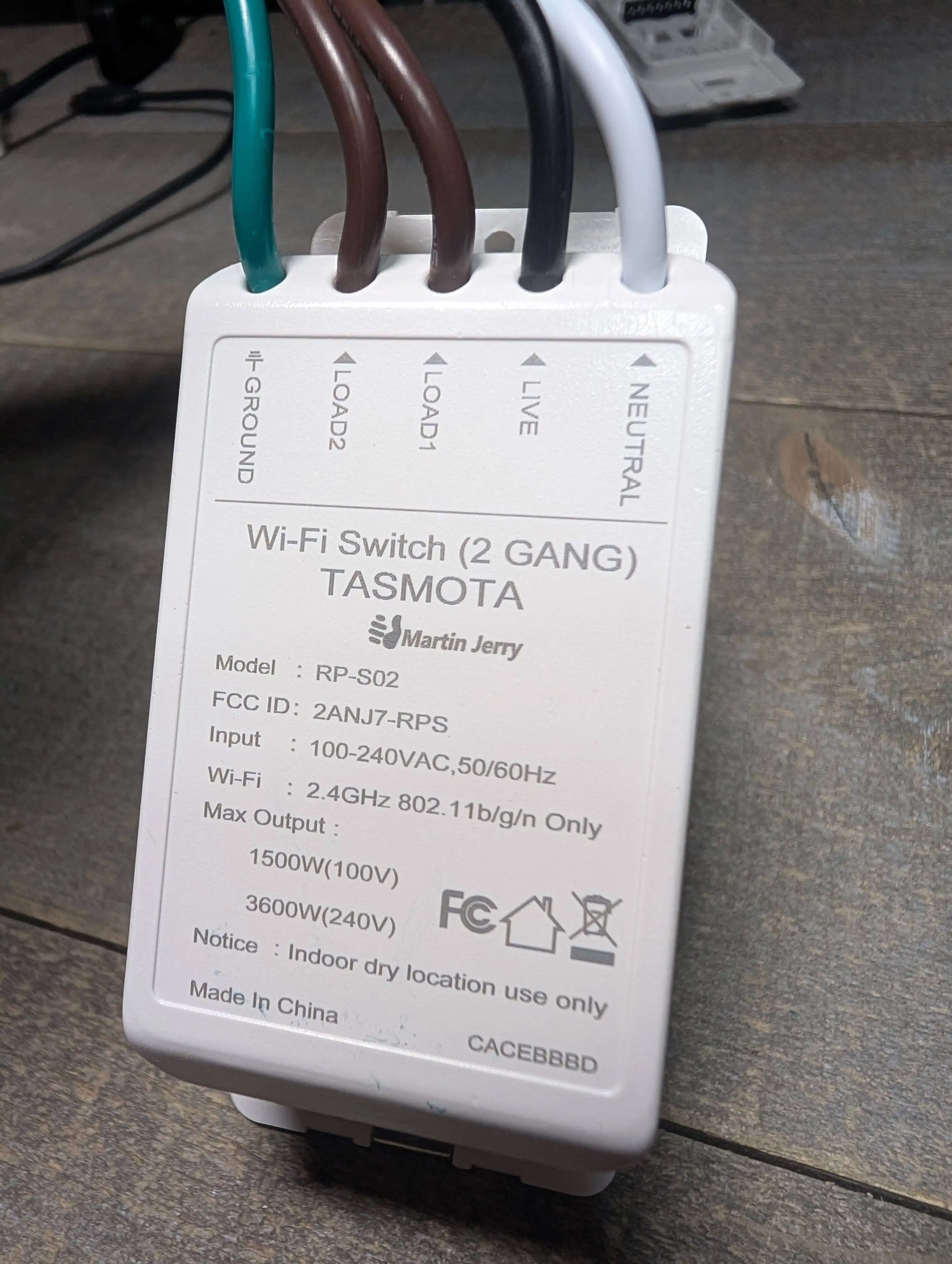
Martin Jerry RP-S02 (Dual Relay)
Dual Relay single width Decora US switch.
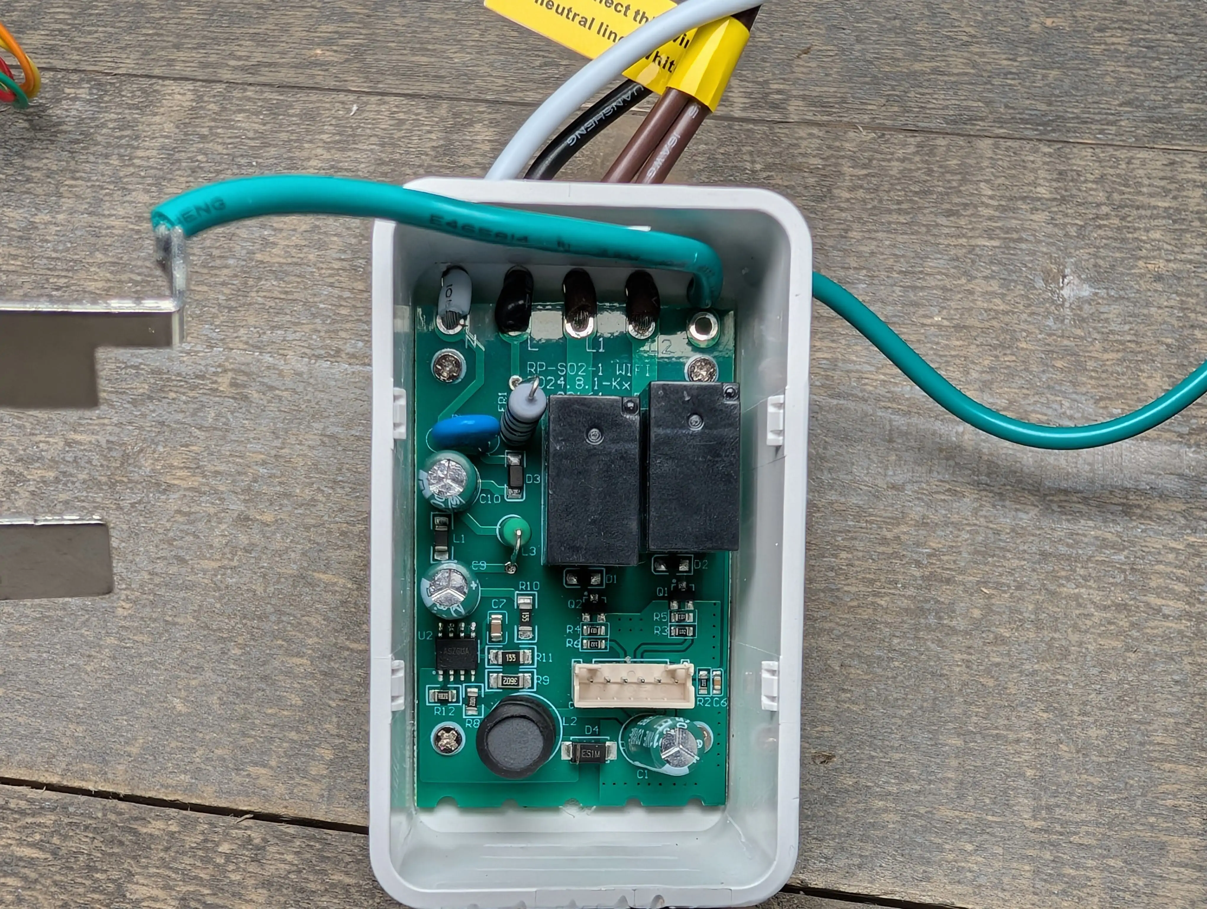
This switch has a White and Red nightlight in a rocker paddle design. There are two small LEDs behind the top rocker to indicate if Relay 1 or Relay 2 are active. The internal relays are rated at only 10 amps, keep this in mind when combining it with a 15 or 20 amp circuit breaker. The white night light brightness is controlled via the dimmer wheel on the top, the red night light is controllable via software.
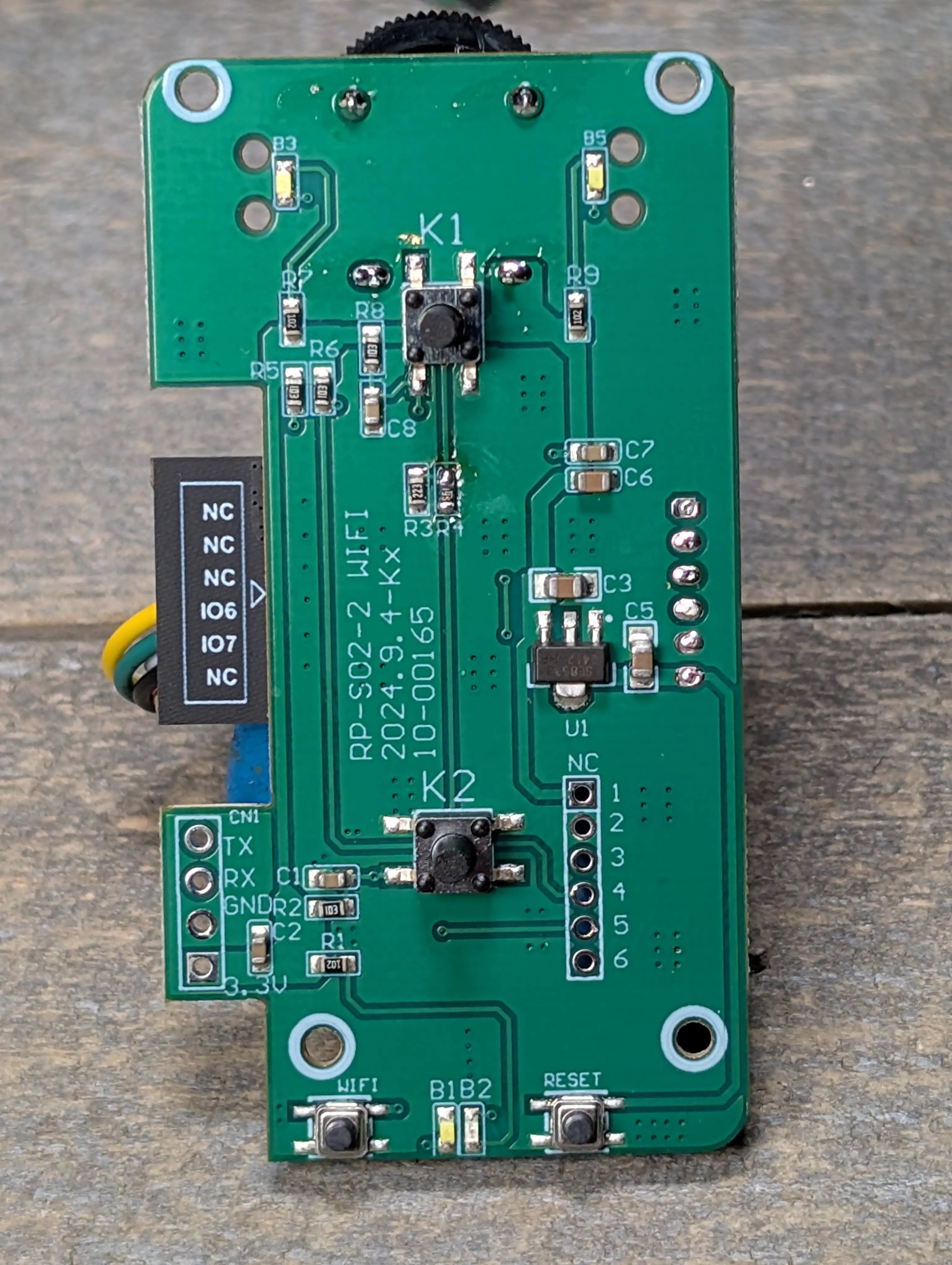
The switch comes preflashed with TASMOTA and Matter enabled on a 4MB ESP32-C3 module. If ESPHome is desired, the switch can easily be converted with a TTL USB adapter and dupont jumpers. NO Soldering is necessary! See Pics Section Below.
YES, you can use this switch as an ESPHome Bluetooth Proxy.
Purchase - Pre-Flashed with TASMOTA Amazon
Detailed video integration into Home Assistant and Teardown
Tasmota Template
{"NAME":"RP-S02 Switch","GPIO":[0,0,225,32,321,320,0,0,576,0,0,0,0,0,0,0,0,0,224,33,0,0],"FLAG":0,"BASE":1}
GPIO Layout
| GPIO | Component | Description |
|---|---|---|
| GPIO02 | Relay2 | Load 2 Wire |
| GPIO03 | Button1 | Top Button |
| GPIO04 | LED1 | Top Left LED |
| GPIO05 | LED2 | Top Right LED |
| GPIO08 | PWM_i | Red Night Light |
| GPIO18 | Relay1 | Load 1 Wire |
| GPIO19 | Button2 | Bottom Button |
TASMOTA Settings
| Setting | Description |
|---|---|
| setoption13 1 | Set Buttons to respond instantly and disable multipress (optional) |
| setoption30 1 | Sets domain to a light (optional) |
TASMOTA Rules
None necessary.
Converting to ESPHome
No soldering is necessary to convert the device to ESPHome!
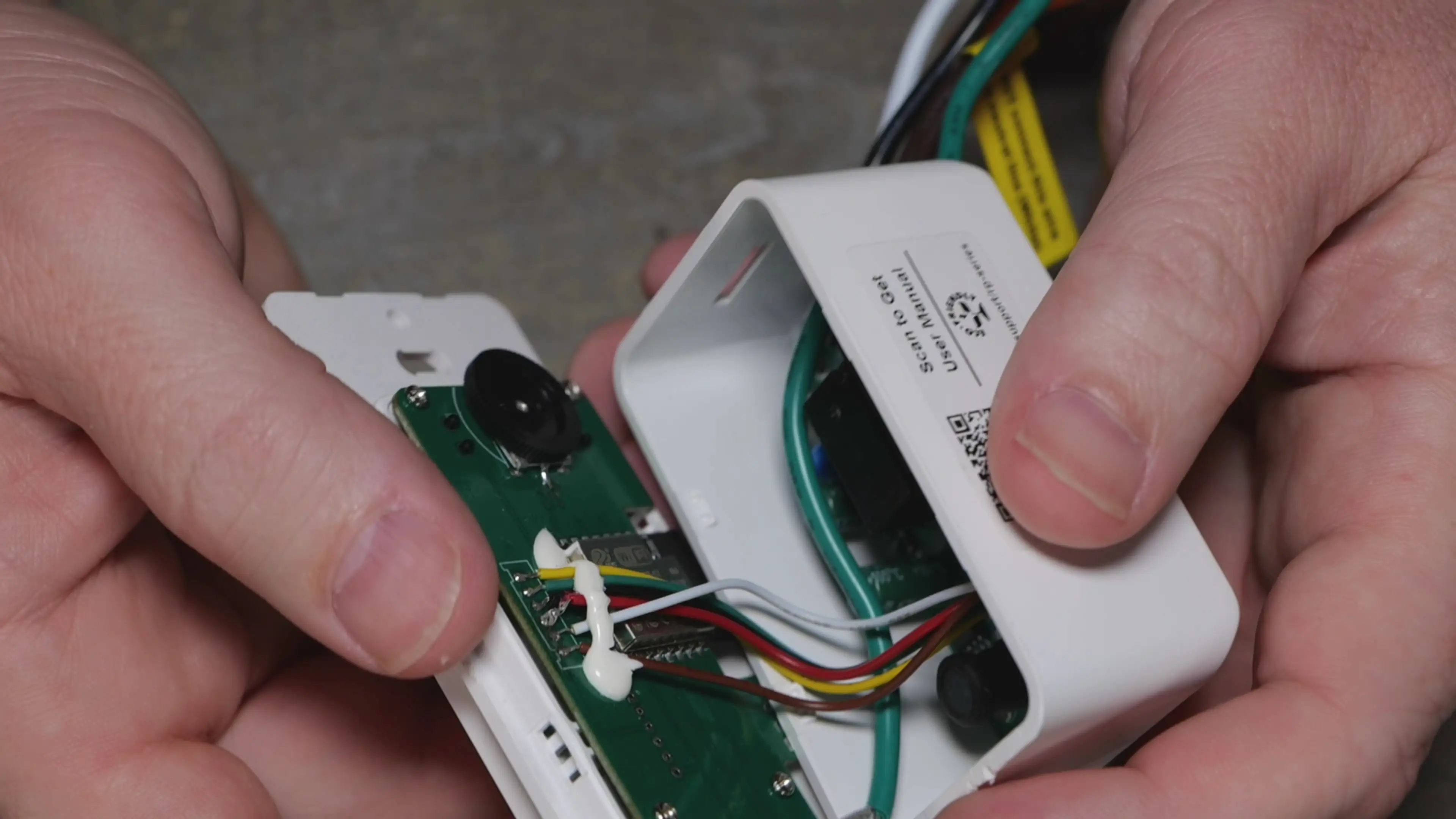
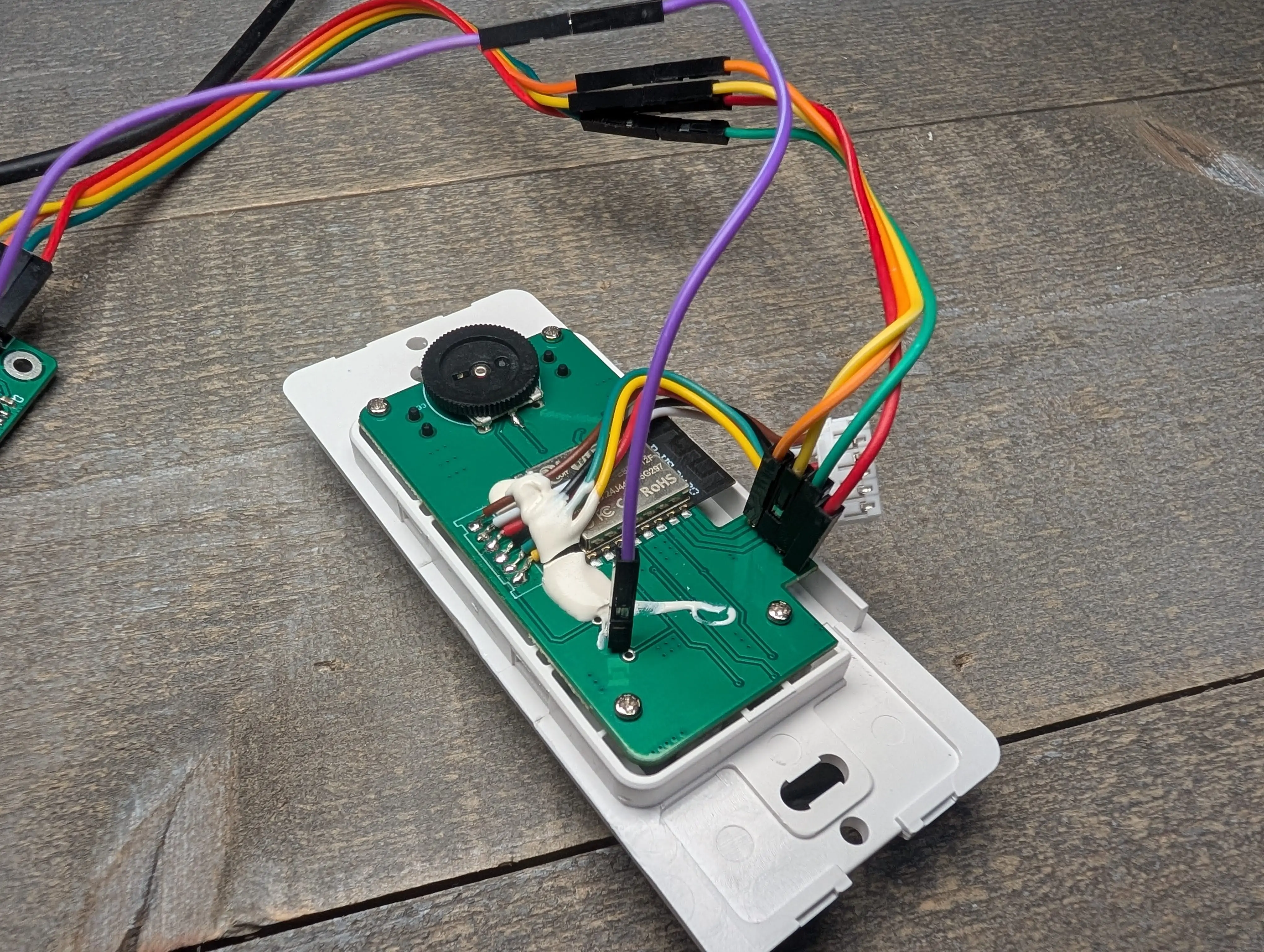
Due to the different flash partitions of ESPHome and TASMOTA, a serial reflash is the best solution to upgrade the switch. The switch has in an internal pin header with the dupont jumper holes broken out for you. They did this for us! You need a USB TTL adapter adapter such as the "little red guy" and a set of female to male dupont jumper wires.
-
Use the YAML below to add the device to the ESPHome compiler dashboard and build the device.
-
Download the factory full image bin file.
-
Connect the dupont wires as shown in the Pics Section below and attach the USB TTL to the computer. GPIO 9 needs to be grounded for at least the first few seconds of power up.
-
Use the ESPHome installer to install your bin file created above.

ESPHome YAML
esphome:
  name: sw-mj-2chan
  friendly_name: sw-mj-2chan
  platformio_options:
    board_build.mcu: esp32c3
    board_build.variant: esp32c3
# added the line below to prevent bootloops when flashing factory bin via serial
    board_build.flash_mode: dio

esp32:
  board: esp32-c3-devkitm-1
  framework:
    type: esp-idf
    sdkconfig_options:
      CONFIG_BT_BLE_50_FEATURES_SUPPORTED: y
      CONFIG_BT_BLE_42_FEATURES_SUPPORTED: y
      CONFIG_ESP_TASK_WDT_TIMEOUT_S: "10"

logger:
api:
captive_portal:
ota:
  - platform: esphome

## Uncomment the section below to enable Bluetooh Proxy Support

#esp32_ble_tracker:
#  scan_parameters:
#    active: true
#bluetooth_proxy:
#  active: true

wifi:
  ssid: !secret wifi_ssid
  password: !secret wifi_password
  ap:

output:
  - platform: gpio
    pin: GPIO5
    inverted: true
    id: led1_output
  - platform: gpio
    pin: GPIO4
    inverted: true
    id: led2_output
  - platform: ledc
    pin: GPIO8
    inverted: true
    id: pwm_light_output

light:
  - platform: binary
    id: led1
    output: led1_output
  - platform: binary
    output: led2_output
    id: led2
  - platform: monochromatic
    output: pwm_light_output
    name: "PWM Light"

# Relays
switch:
  - platform: gpio
    pin: GPIO18
    name: "Relay 1"
    id: relay_1
    on_turn_on:
      - light.turn_on: led1
    on_turn_off:
      - light.turn_off: led1
    restore_mode: RESTORE_DEFAULT_OFF

  - platform: gpio
    pin: GPIO2
    name: "Relay 2"
    id: relay_2
    on_turn_on:
      - light.turn_on: led2
    on_turn_off:
      - light.turn_off: led2
    restore_mode: RESTORE_DEFAULT_OFF

binary_sensor:
  - platform: gpio
    pin:
      number: GPIO3
      mode: INPUT_PULLUP
    id: button1
    on_press:
      - switch.toggle: relay_1

  - platform: gpio
    pin:
      number: GPIO19
      mode: INPUT_PULLUP
    id: button2
    on_press:
      - switch.toggle: relay_2
Pics