3-Way Wiring Diagrams
Here are some examples on how a light switch is wired up in a 3 way configuration with different smart models and types
In the below diagrams we'll call the switch that has mains power connected to it the Main Switch
Then the Switch that has the load attached to it we'll call the Load Switch or Remote Switch
Standard Switches (non-smart)
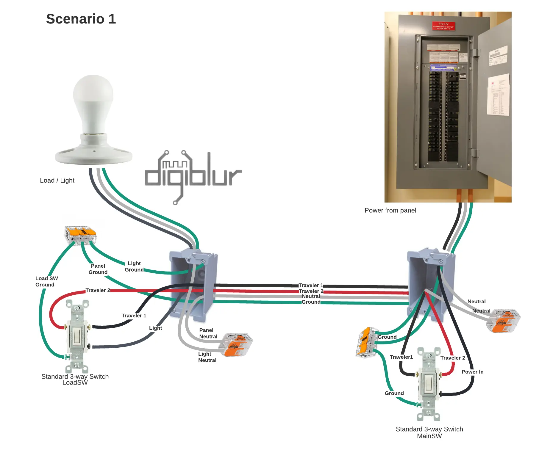
Scenario 1
In this scenario the Power comes in on one box and the load (light) is on a different box
Scenario 2
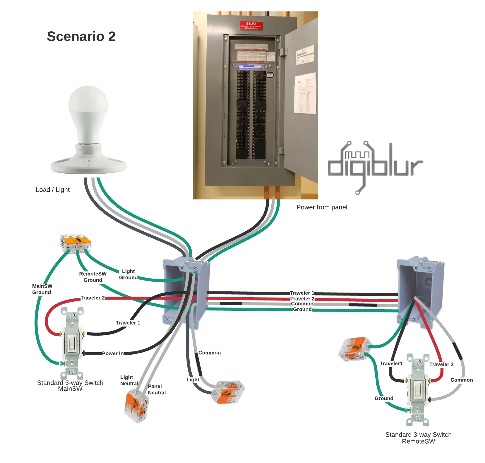
In this scenario the Power and load (Light) comes in on one box and there is a remote switch in another box
The neutral wire is used to transfer the power to the light in the first box
You'll use the normally white neutral wire as the common. Make sure to put black electrical tape to indicate it's being repurposed as power. This will help you avoid accidentially tying it in with the other neutral wires in the box and causing a short
Martin Jerry ST01
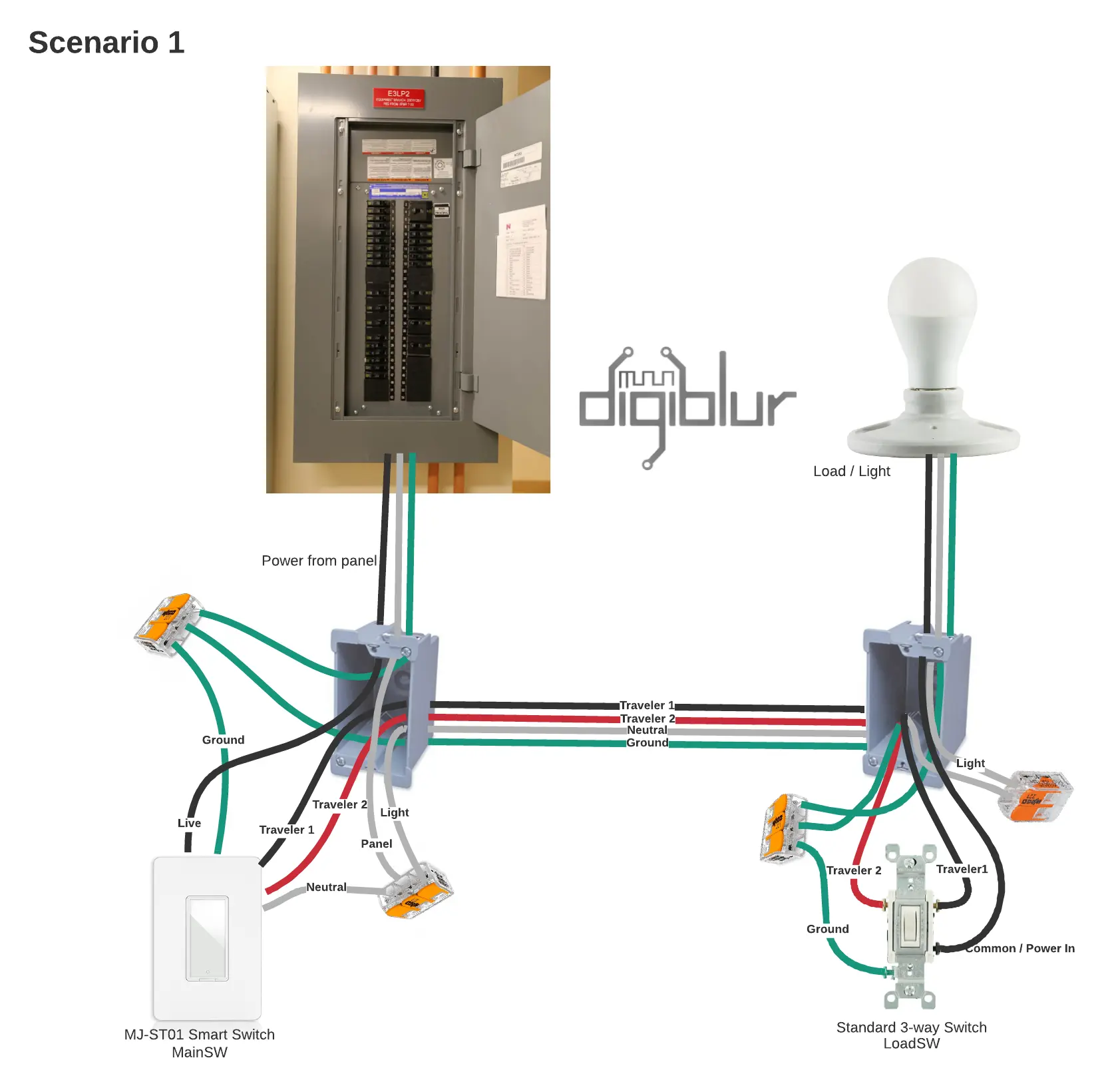
Scenario 1
In this scenario the power comes into the Martin Jerry ST01 and the load (light) is on the remote switch a different box
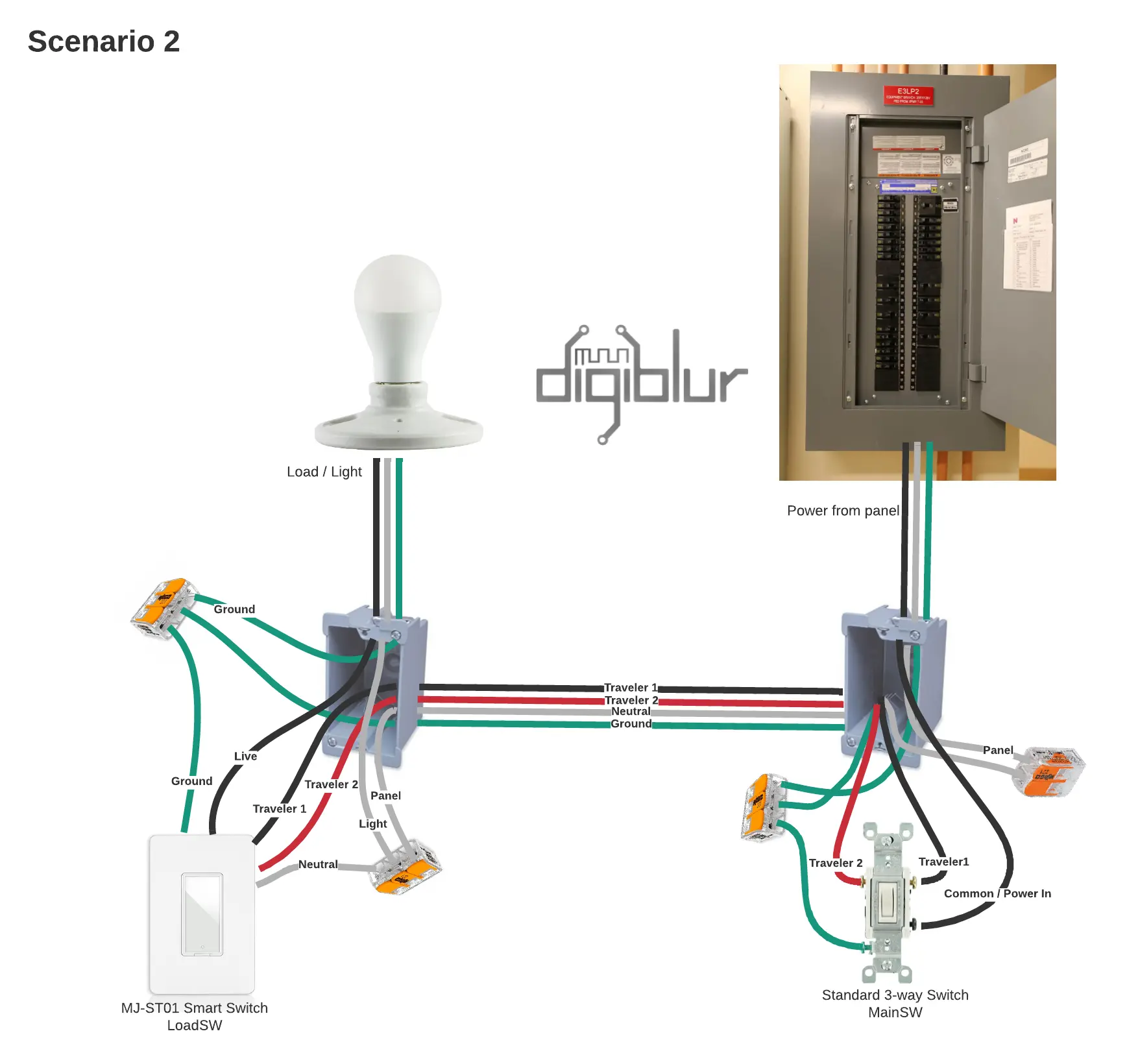
Scenario 2
In this scenario the power comes into the standard 3 way switch and the load (light) is on the Martin Jerry ST01 switch the remote box
Scenario 3
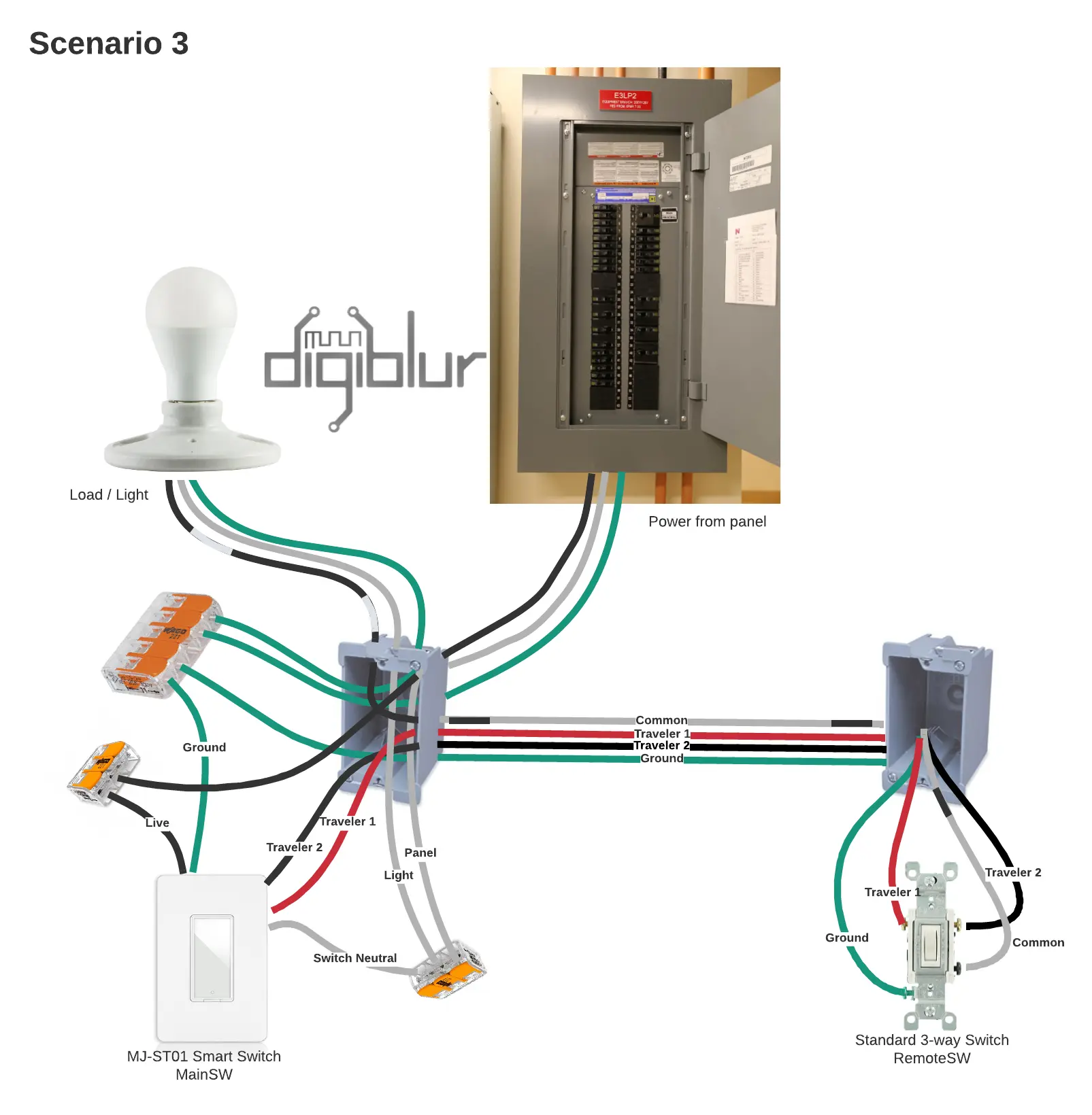
In this scenario the Power and load (Light) comes in on one box where you'll have the Martin Jerry ST01 and there is a remote switch in another box The neutral wire is used to transfer the power to the light in the first box You'll use the normally white neutral wire as the common. Make sure to put black electrical tape to indicate it's being repurposed as power. This will help you avoid accidentially tying it in with the other neutral wires in the box and causing a short
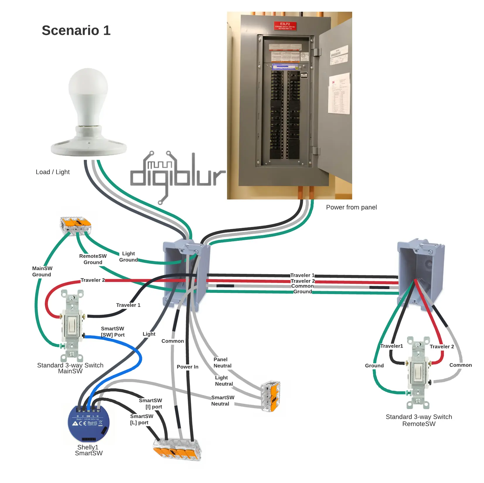
Shelly 1
Scenario 1
In this scenario it's much like the standard 3-way switches doing the real work and instead of outputing the power directly to the light. You pipe the power to the switch port on the shelly1 and it will then trigger to it's out port to the light.
