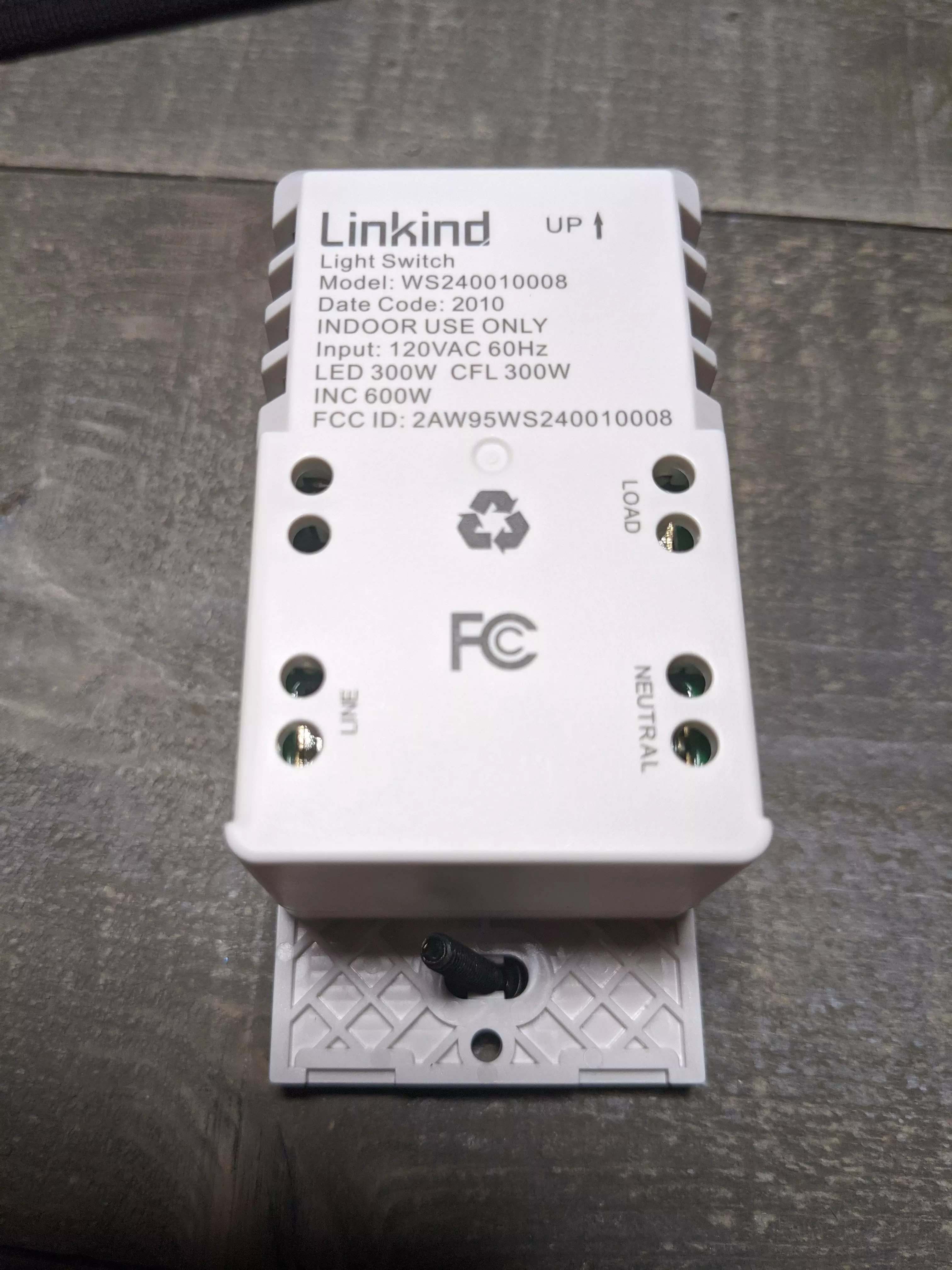
Linkind Switch WS240010008
These are no longer available on Amazon but the page was brought over from the old website for historical purposes and requests.
Buy the 1 pack on Amazon
Buy the 4 pack on Amazon
Can we flash Tasmota on it? YES!
Tasmota Template
{"NAME":"Linkind Switch ESP32Solo WS240010008","GPIO":[0,0,0,0,0,224,1,1,0,0,288,0,1,1,0,0,0,0,0,0,0,576,321,0,0,0,0,0,33,32,0,0,0,0,0,0],"FLAG":0,"BASE":1}
ESPHome YAML
But can we flash ESPHome on it instead? YES! (Thanks to zeroping!)
# Basic Config
#---
#substitutions:
#  https://esphome.io/guides/configuration-types.html#substitutions
#  device_name: esp-br3 # hostname & entity_id

esphome:
  name: ${device_name}

esp32:
  board: esp32dev
  framework:
    type: esp-idf
    sdkconfig_options:
      CONFIG_FREERTOS_UNICORE: y

wifi:
  # https://esphome.io/components/wifi

#captive_portal:
# doesn't work under esp-idf

#web_server:
  #port: 80
  # https://esphome.io/components/web_server.html
# doesn't work under esp-idf

logger:
  # https://esphome.io/components/logger

api:
  #password: !secret esphome_api_password
  # https://esphome.io/components/api
  reboot_timeout: 0s #disable auto-reboot if homeassistant is not connecting

ota:
  platform: esphome
  #password: !secret esphome_ota_password
  # https://esphome.io/components/ota

light:
  - platform: binary
    id: relaylight
    name: ${device_name} relay
    output: relay
    on_turn_on:
      - output.turn_on:
          id: green_led
    on_turn_off:
      - output.turn_off:
          id: green_led

  - platform: binary
    id: greenlight
    name: ${device_name} green led
    output:  green_led

  - platform: status_led
    #id: redlight
    name: ${device_name} red led
    pin: GPIO26

output:
  - platform: gpio
    # https://esphome.io/components/output/gpio.html
    pin: GPIO5
    inverted: false
    id: relay

  - platform: gpio
    # https://esphome.io/components/output/gpio.html
    pin: GPIO14
    inverted: false
    id: green_led

    #pin: GPIO25 might or might not be hooked up to something? Not clear.

  #- platform: gpio
    ## https://esphome.io/components/output/gpio.html
    #pin: GPIO26
    #inverted: false
    #id: red_led
  #replaced with the status_led entity above

binary_sensor:

  - platform: gpio
    # https://esphome.io/components/binary_sensor/gpio.html
    pin:
      number: GPIO32
      inverted: true
      mode: INPUT_PULLUP
    name: ${device_name} Top Button
    internal: false
    on_click:
      - light.turn_on: relaylight

  - platform: gpio
    # https://esphome.io/components/binary_sensor/gpio.html
    pin:
      number: GPIO33
      inverted: true
      mode: INPUT_PULLUP
    name: ${device_name} Bottom Button
    internal: False
    on_click:
      - light.turn_off: relaylight
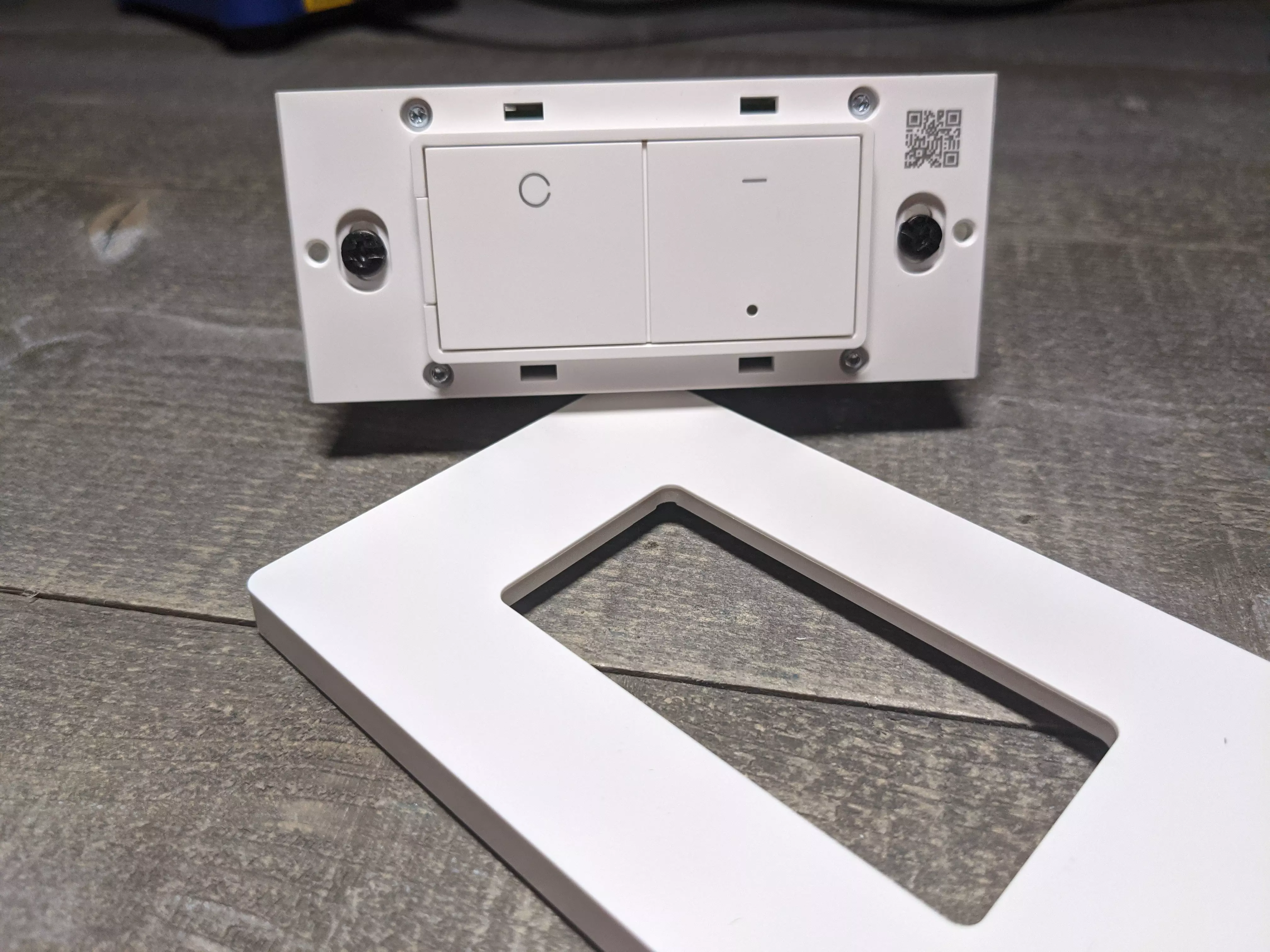
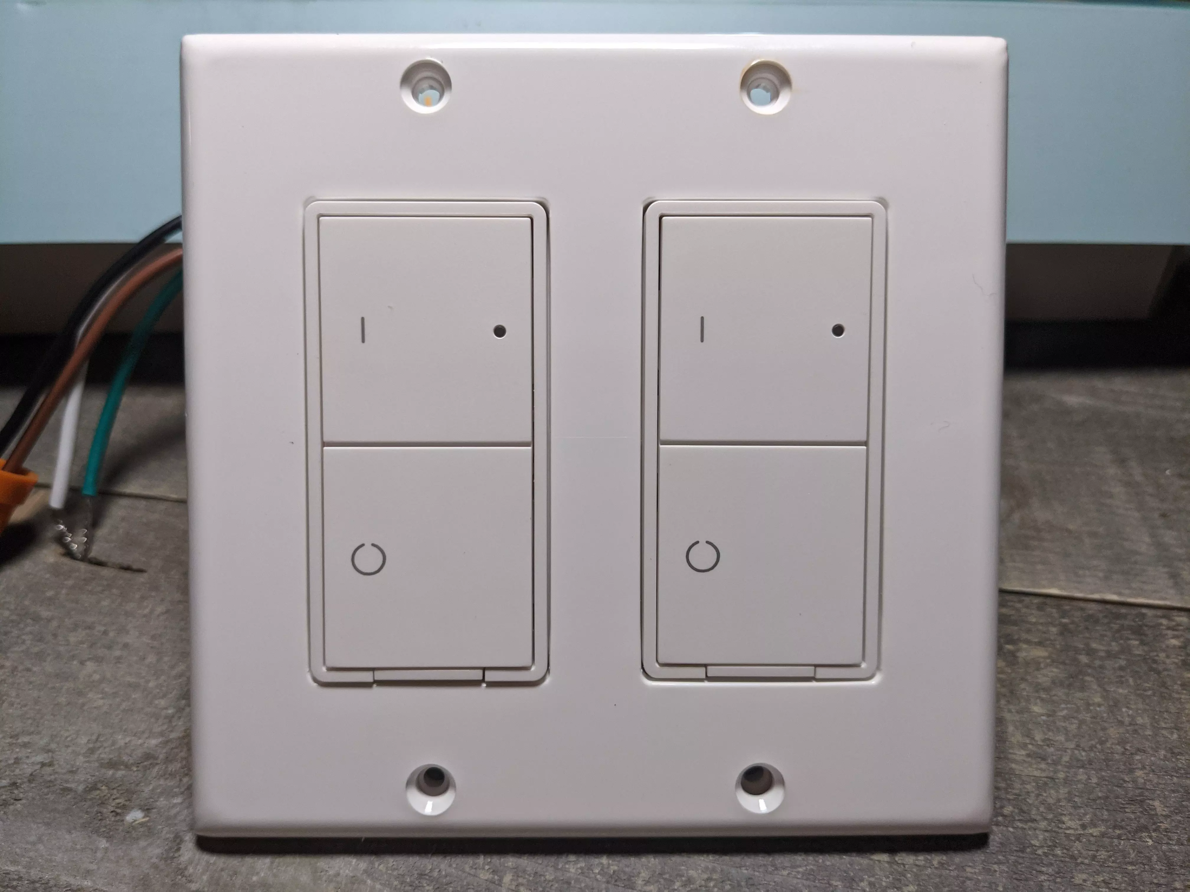
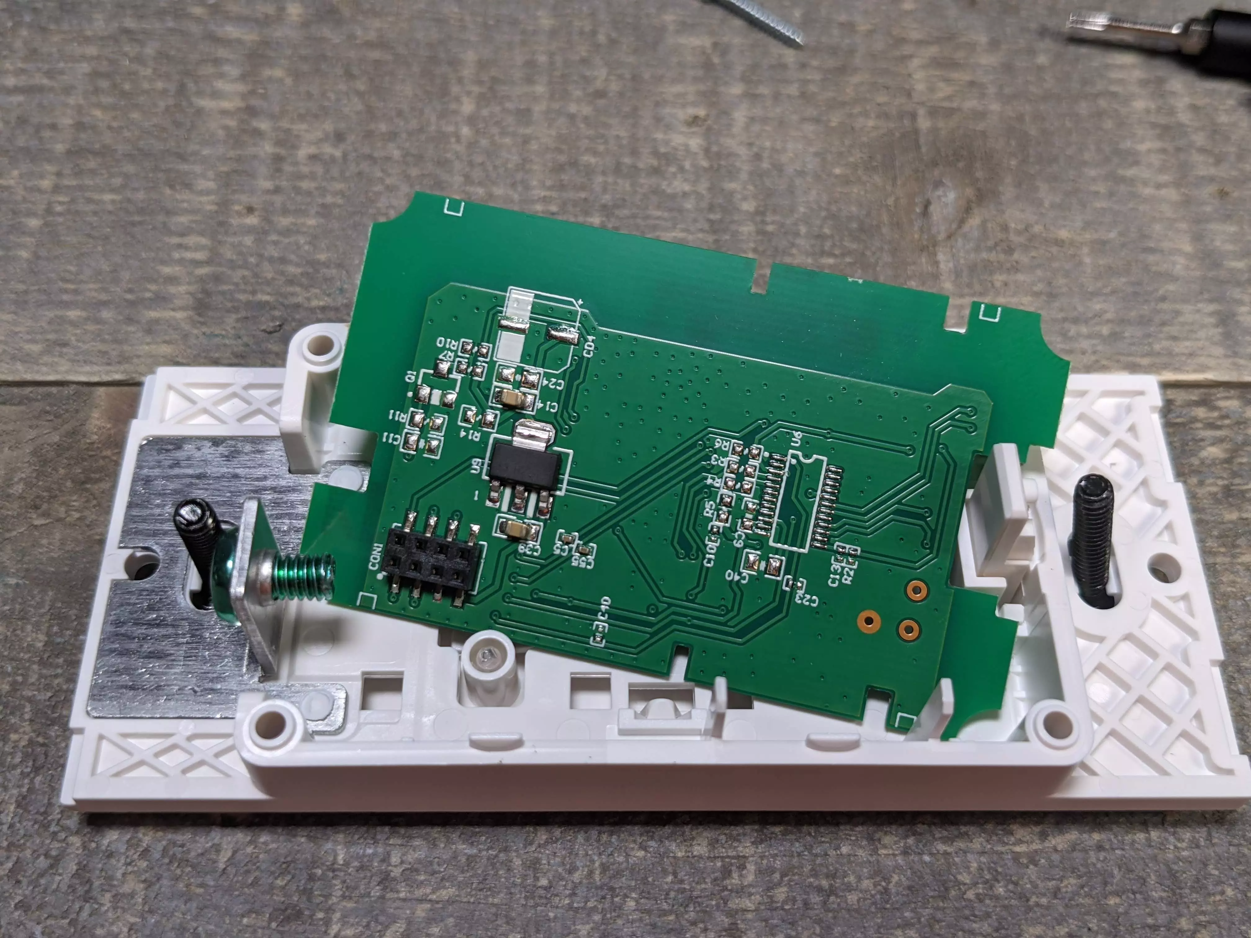
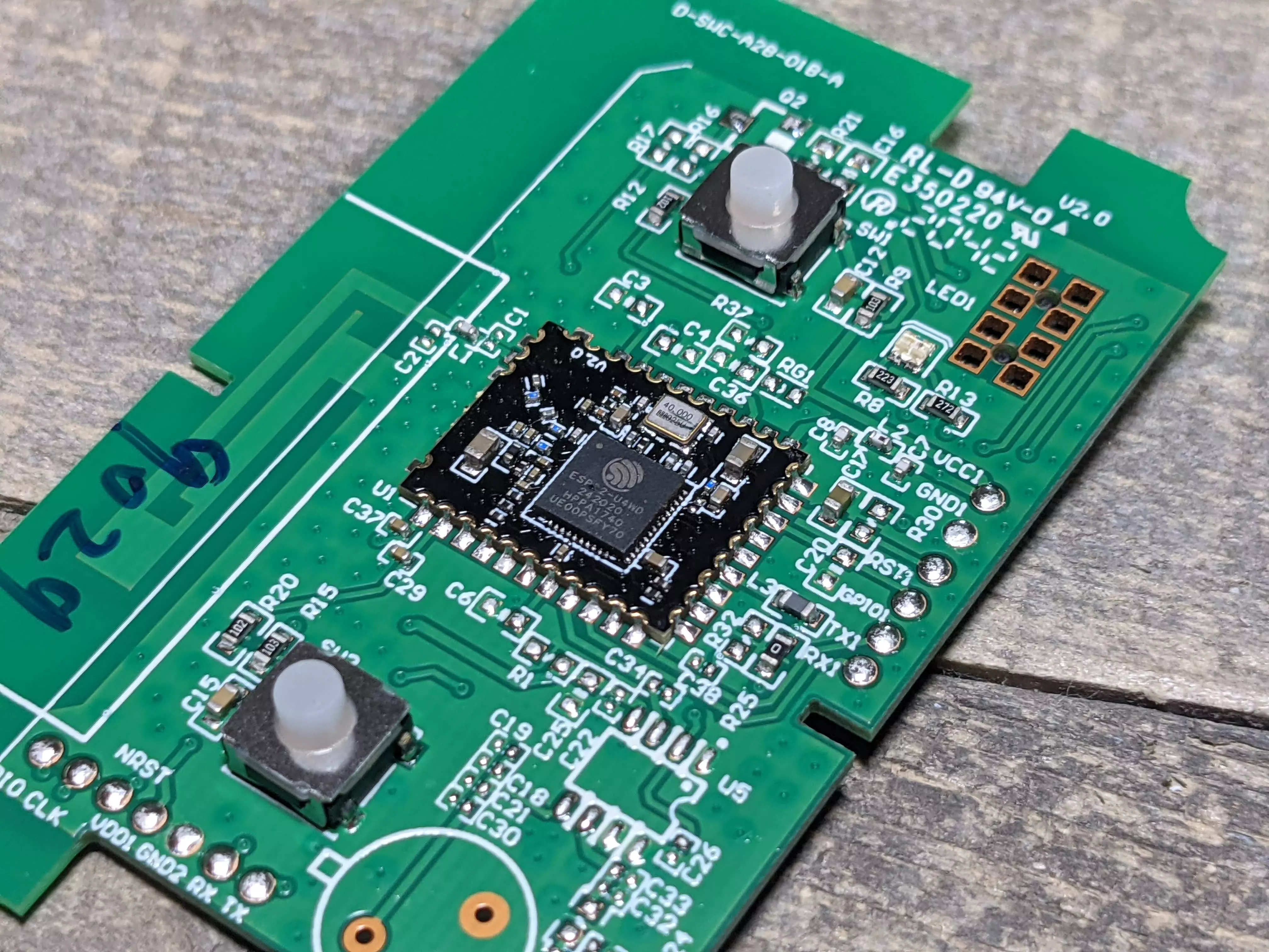
The Linkind Smart Switch is rather unique. It uses an ESP32 chipset with Bluetooth support, two independent buttons, two independent LEDs (behind the small hole) of green/red and one relay. It ships with a non branded white screwless decora faceplate. The switch can also be used in multi-gang boxes as they have the additional mounting holes.
Bought the dimmer? The instructions for flashing/disassembly will be the same except when you get to the software to push over to the dimmer itself. Software will be linked down below for the dimmer in the steps.
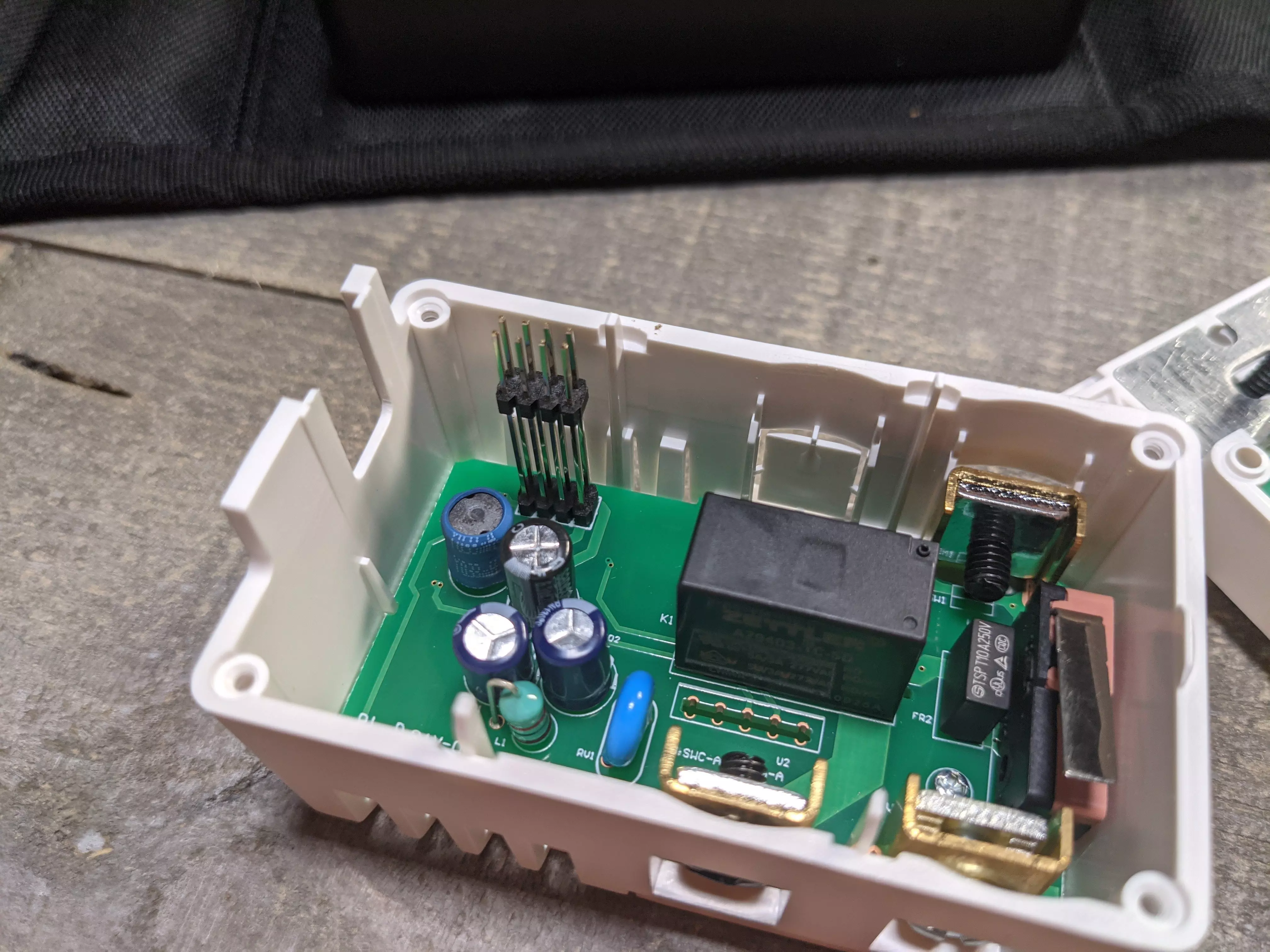
To open the switch, there 4 small torx screws in the face. I used the one out of the iFixIt kit but a small flat head screwdriver could also be used. Remove the four screws on the face and pull it straight up. There will be some tension as 8 header pins intersect the faceplate board.
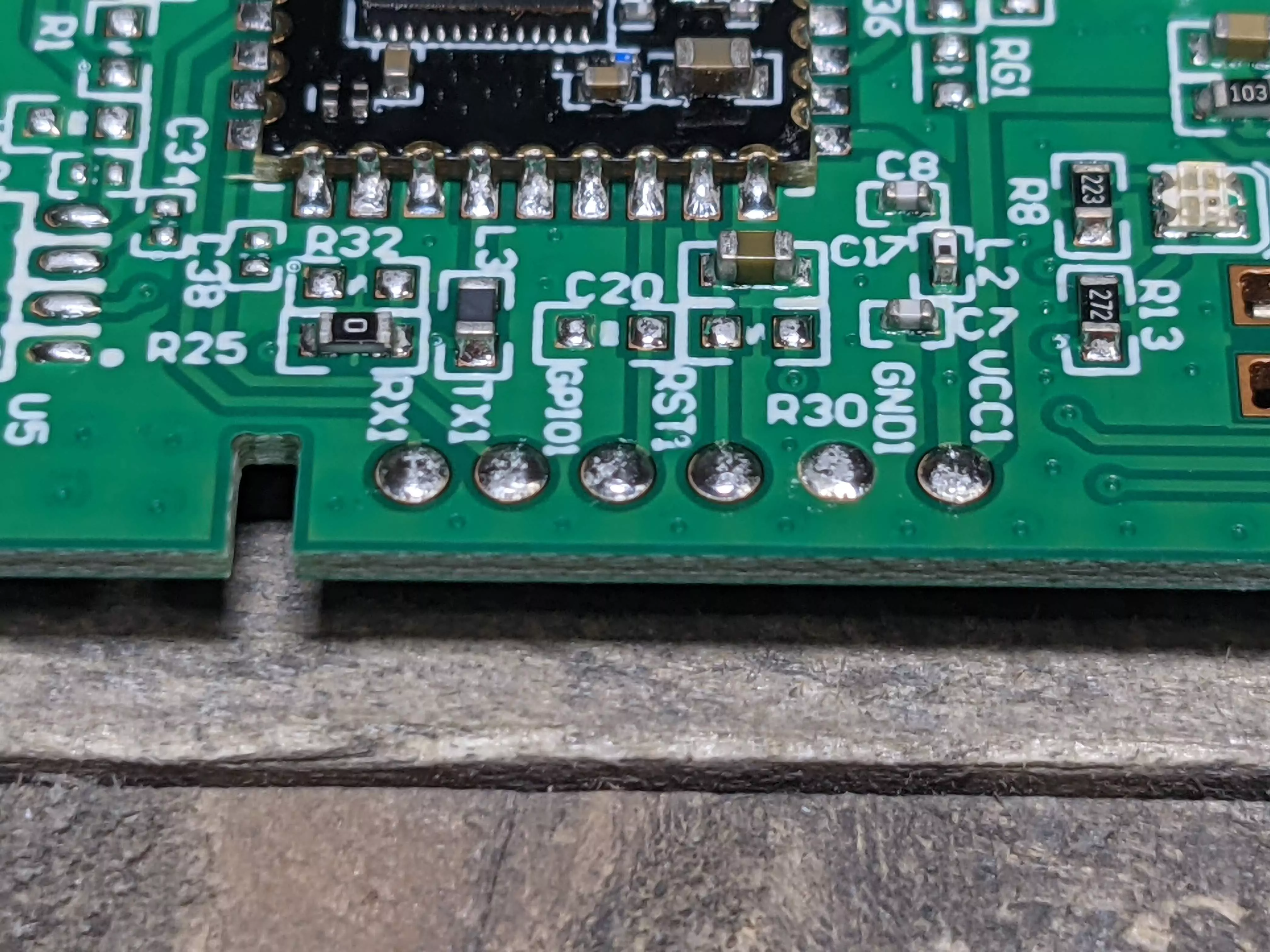
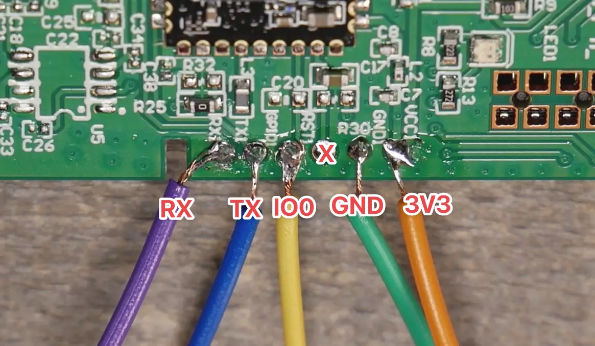
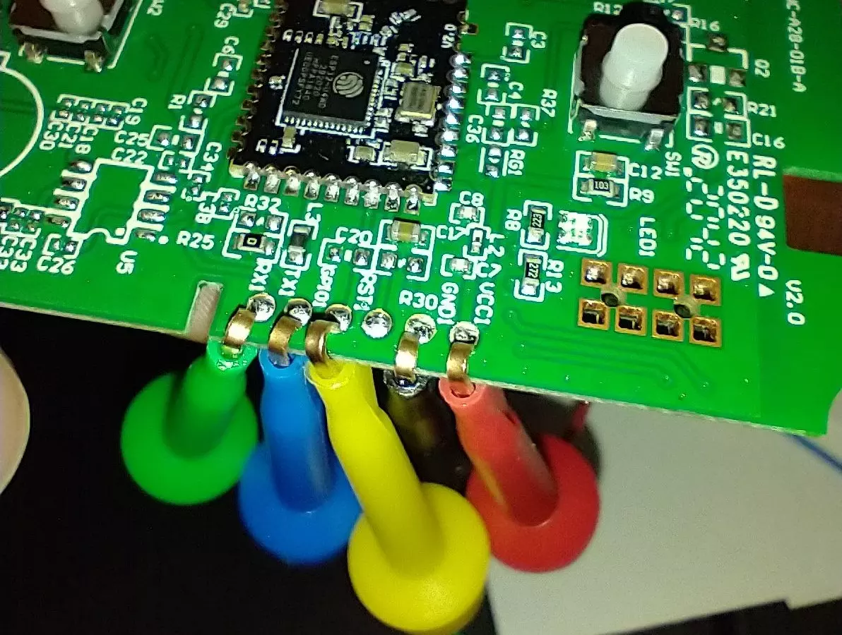
You can choose to either bend some clips or solder to the pads. Remember to connect RX to TX and TX to RX on your USB TTL flasher. The pads are as follows from Left to Right; RX, TX, GPIO Zero, skip RST, Ground, and 3.3 volts. DO NOT apply 5V to this pad, the magic smoke might come out. GPIO Zero will also need to be connected to ground either for the first few seconds while power is applied or the entire flashing time.
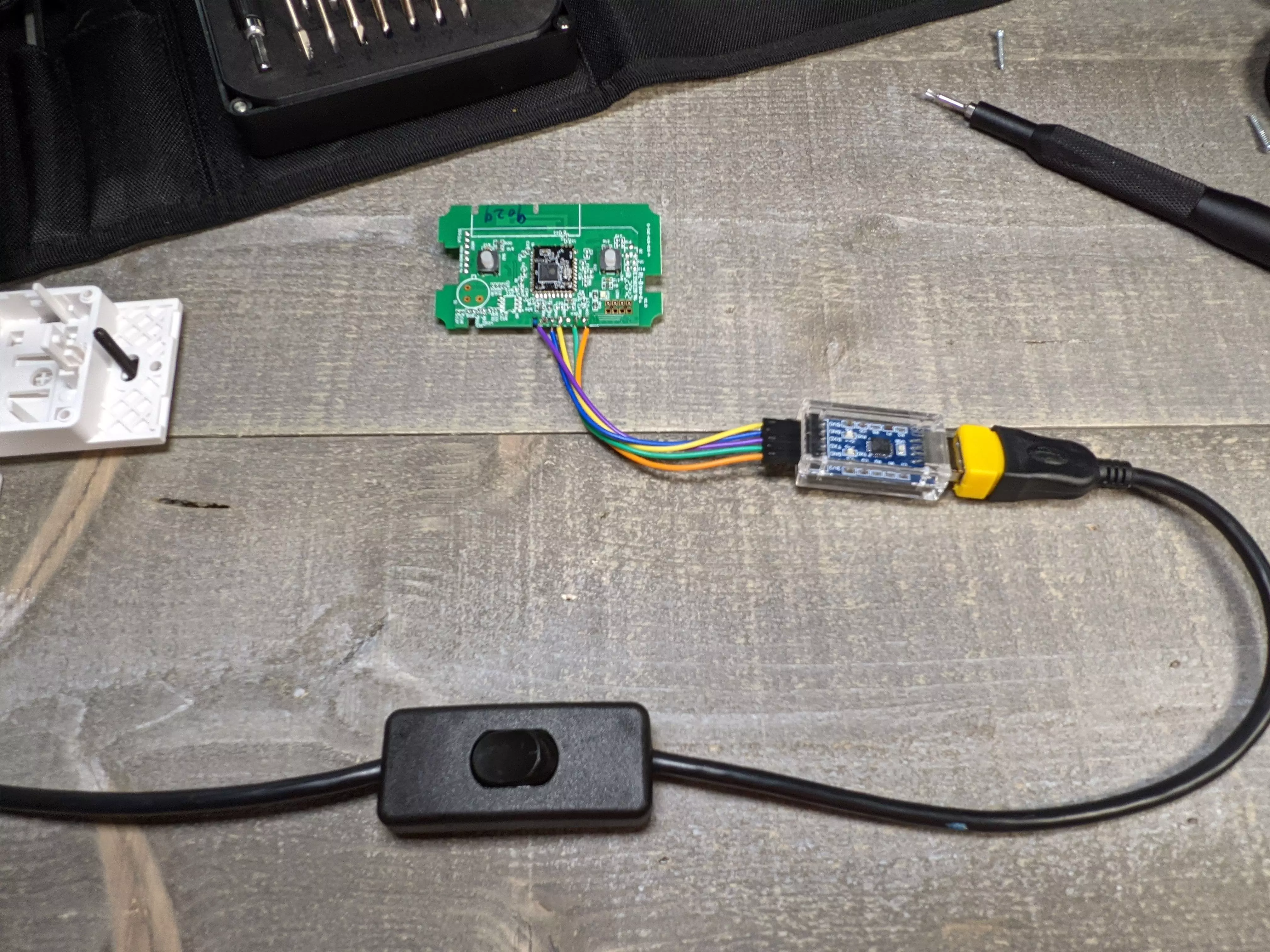
Clips with dupont female dupont ends Dupont jumper wires
I use a USB cable with an inline power switch to make flashing easier but it isn't required. The ESP32 on this switch requires the Tasmota32 Solo1 version bin file. You can flash this version straight from your browser by going to https://tasmota.github.io/install/
But I want to use ESPHome!?!? Zeroping has the code for you
If you bought the dimmer, go ahead and follow through the same steps. There is an additional file to push to the switch as the last step.
Select Tasmota32 Solo1, check reset defaults and click install. If you want Bluetooth scanning too, scroll all the way down and choose "Tasmota32 Solo1 Thermostat + BLE". NOTE: It has been found due to the ESP32, power requirements are higher and some USB TTL adapters may not be able to power the device properly and may fail during the flash and/or the WiFi setup of the device. I was able to flash and power the switch with this adapter CP2102 USB TTL
Paste in the following command all on one line and hit enter (if you bought the dimmer skip to the dimmer subsection below).
backlog template {"NAME":"Linkind Switch ESP32Solo WS240010008","GPIO":[0,0,0,0,0,224,1,1,0,0,288,0,1,1,0,0,0,0,0,0,0,576,321,0,0,0,0,0,33,32,0,0,0,0,0,0],"FLAG":0,"BASE":1} ; Delay 1 ; Module 0
Optional: If a Red LED while Off and Green LED while On is desired paste the following rule into the Tasmota console. If you want opposite colors, edit the template in the configure template screen and transpose Led_i with Led and vice versa. The "i" stands for inverted. Copy the below rule as one line to the Tasmota console:
Rule1 on power1#state do backlog ledpower1 %value%; ledpower2 %value% endon
      on power1#boot do backlog ledpower1 %value%; ledpower2 %value% endon
Activate the Rule with
Rule1 1
The ESP32 Solo supports Bluetooth scanning too with the correct bin file. Currently use the Tasmota32 Solo1 Thermostat + BLE file. Bluetooth was tested by a couple of us including myself extensively, it seems to work well even being a single core ESP32. Check out the Tasmota Blerry Project.
Pics