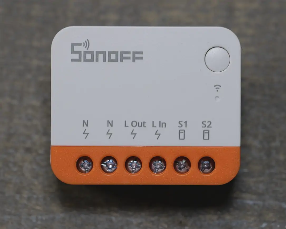
Sonoff Mini R4
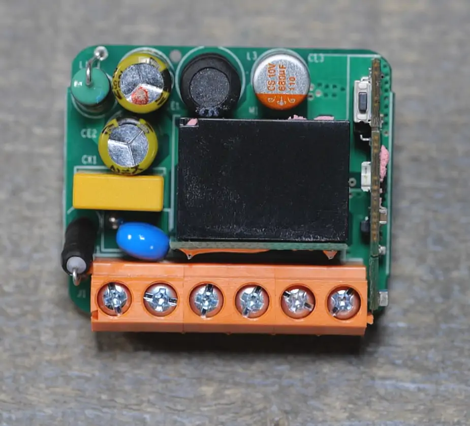
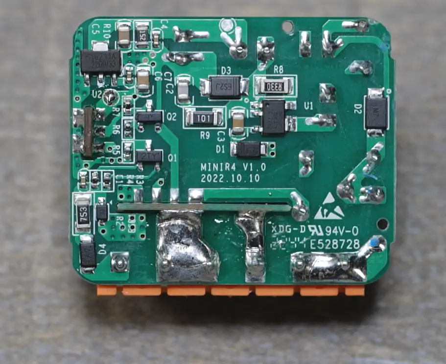
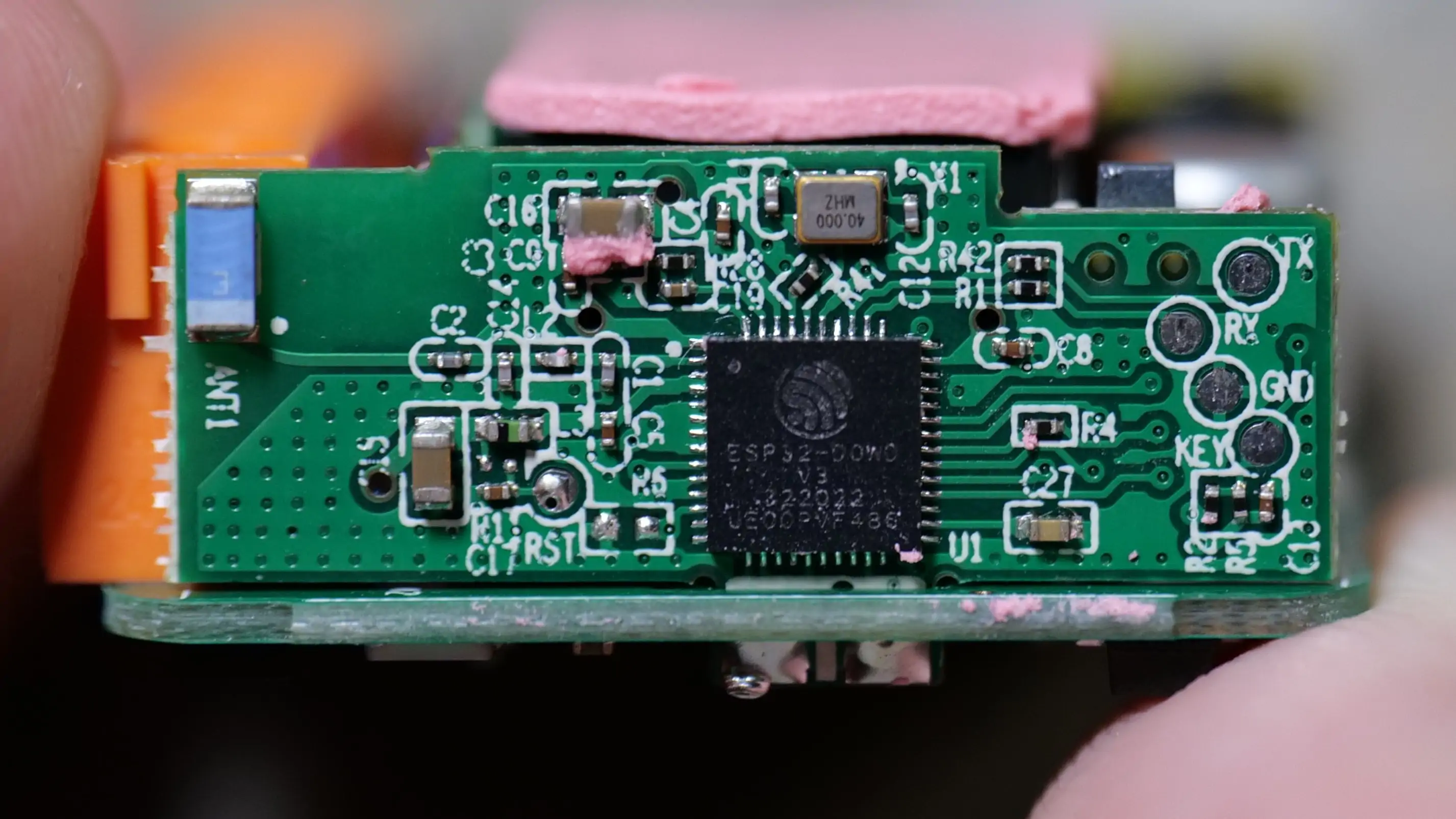
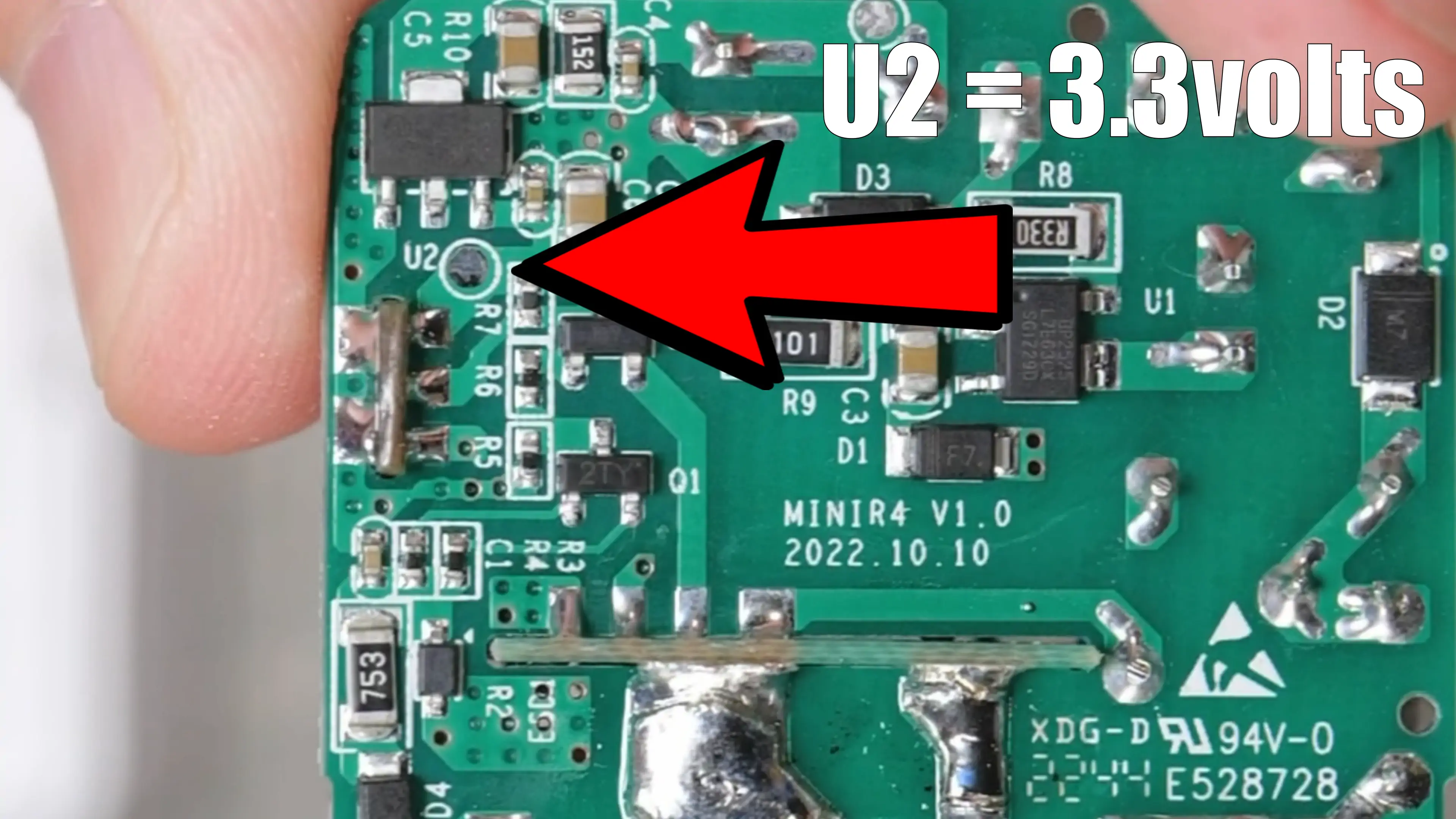
SONOFF MiniR4 Extreme series. 10A single relay. 100-240VAC 50 / 60 hz. With dual core ESP32. Flashing is done via the exposed pin headers on the board (see pics below) KEY is GPIO 0 and 3.3vdc is found on the U2 pad on the bottom.
Purchase - Not Available Yet
Video Setup
TASMOTA Template
{"NAME":"Sonoff MiniR4 ESP32","GPIO":[32,1,1,1,1,1,1,1,0,1,1,1,1,1,1,576,0,1,1,1,0,1,224,160,0,0,0,0,1,1,1,1,1,0,0,1],"FLAG":0,"BASE":1}
TASMOTA Settings
| Setting | Description |
|---|---|
| switchmode1 1 | Set if using a non-monetary push button/switch |
GPIO Layout
| GPIO | Component | Description |
|---|---|---|
| GPIO00 | Button1 | Button |
| GPIO19 | LedLink_i | Inverted LED |
| GPIO26 | Relay1 | Relay for Load |
| GPIO27 | Switch1 | S1/S2 input |
ESPHome YAML
substitutions:
  display_name: minir4

esphome:
  name: minir4

esp32:
  board: esp32dev
  framework:
    type: arduino

wifi:
  ssid: !secret wifi_myssid
  password: !secret wifi_mypass
  ap:
    ssid: ${display_name}_AP
    password: !secret wifi_mypass
    ap_timeout: 3min

captive_portal:

esp32_ble_tracker:
  scan_parameters:
    interval: 300ms
    window: 100ms
    active: true

bluetooth_proxy:
  active: true

logger:

ota:
  platform: esphome

api:

switch:
  - platform: gpio
    name: ${display_name} Relay
    pin:
      number: GPIO26
      inverted: false
    id: relay
    on_turn_on:
      - light.turn_on: relay_led
    on_turn_off:
      - light.turn_off: relay_led
  - platform: restart
    name: ${display_name} Restart

output:
  - platform: gpio
    pin: GPIO19
    inverted: True
    id: relay1_led_gpio

light:
  - platform: binary
    name: "Relay LED"
    id: relay_led
    internal: true
    output: relay1_led_gpio

binary_sensor:
  - platform: gpio
    internal: true
    pin:
      number: GPIO27
      mode: INPUT_PULLUP
      inverted: false
    name: ${display_name} Switch
    on_state:
      - switch.toggle: relay
  - platform: gpio
    internal: true
    pin:
      number: GPIO0
      mode: INPUT_PULLUP
      inverted: false
    name: ${display_name} Button
    on_press:
      - switch.toggle: relay
Pics