DrChop Corner Floor Lamp

Purchase via Amazon
1/03/2023 - This device has a realtek chip. We will swap in ESP32-C3-12F Chip
Pinouts
GPIO Layout
| GPIO | Component | Description |
|---|---|---|
| GPIO3 | IR | Infrared receiver |
| GPIO5 | Button 2 | |
| GPIO21 | LEDs | 48 LEDs in length BRG color order |
| GPIO18 | Button 1 | |
| GPIO19 | Button 0 |
Additional Hardware
You'll need to buy yourself an
Pre-Flash ESP-C3-12F
Chip Flashing
Our ESP Burner isn't designed for use with the ESP32-C3 in particular but because they are both the 12F format it will work. It will require for use to a few jumper wires. You can see which pins to apply here in this diagram:
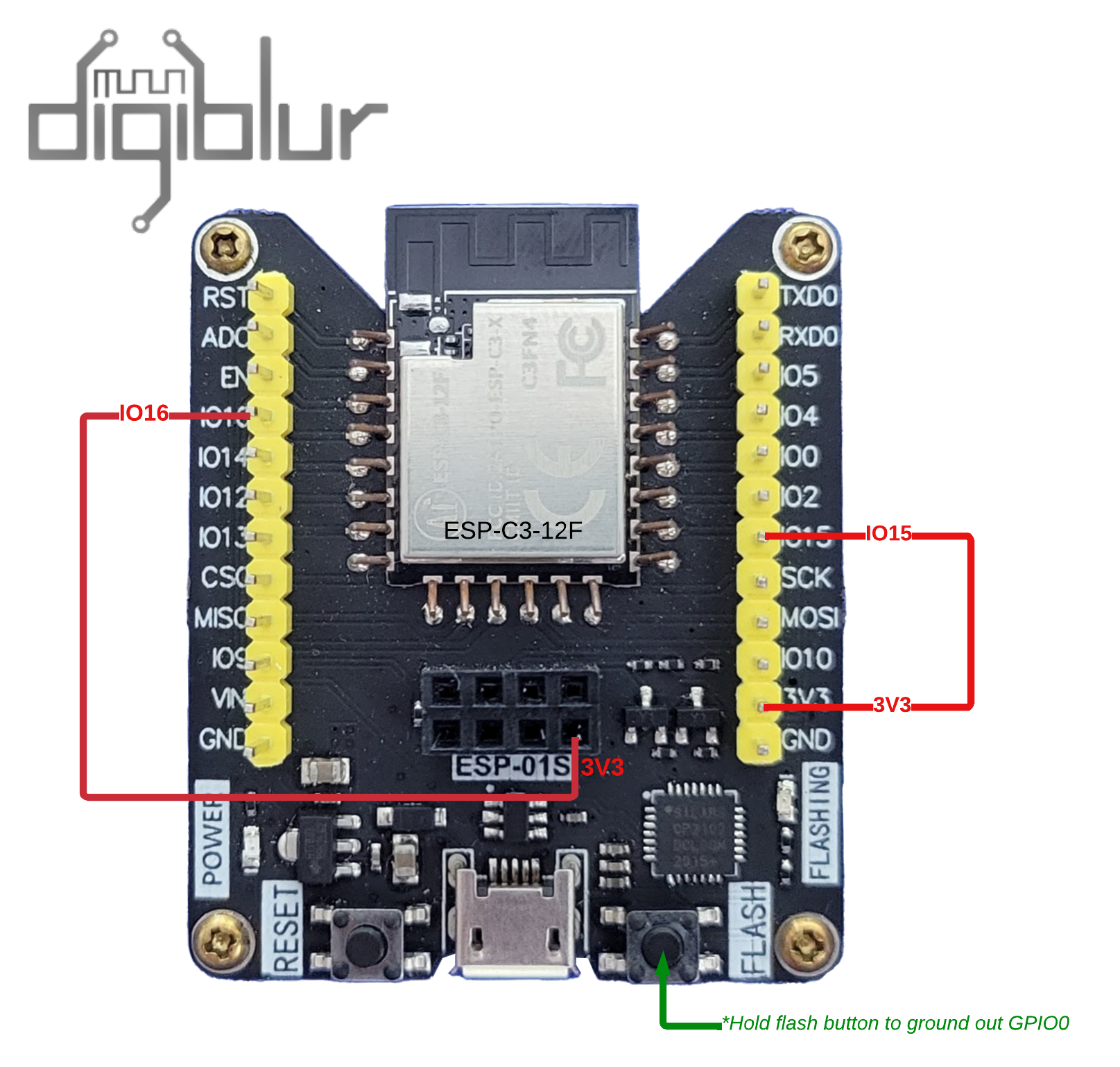
We want to flash WLED onto the chip but because this is an ESP32 chip you need to flash the factory firmware image then use wled
Compile WLED
To setup VSCode/Platformio to compile visit here
We need to comment out or delete this line in https://github.com/Aircoookie/WLED/blob/main/wled00/pin_manager.cpp#L246
Line to ommit because we need to use GPIO pin 18 and 19:
if (gpio > 17 && gpio < 20) return false; // 18-19 USB-JTAG
Here is a sample of the platformio_override.ini file used
[platformio]
default_envs = WLED_drchop_corner_lamp

[env:WLED_drchop_corner_lamp]
board = esp32-c3-devkitm-1
platform = ${common.platform_wled_default}
platform_packages = ${common.platform_packages}
framework = arduino
board_build.partitions = tools/WLED_ESP32_4MB_1MB_FS.csv
upload_speed = 460800
build_unflags = ${common.build_unflags}
lib_deps = ${esp32c3.lib_deps}
After you build/compile the code it'll show up in the directory build_output/release/WLED_VERSION_drchop_corner_lamp.bin
Pre-Compiled WLED
WLED-0.14.0-b1 with GPIO pin 18 and 19 enabled
Use ESPtool to flash it to the memory spaces 0x0
esptool.py write_flash 0x0 wled-0.14.0-b1-esp32c3-4m-gpio1819enabled.factory.bin
Open it
Pry the back open
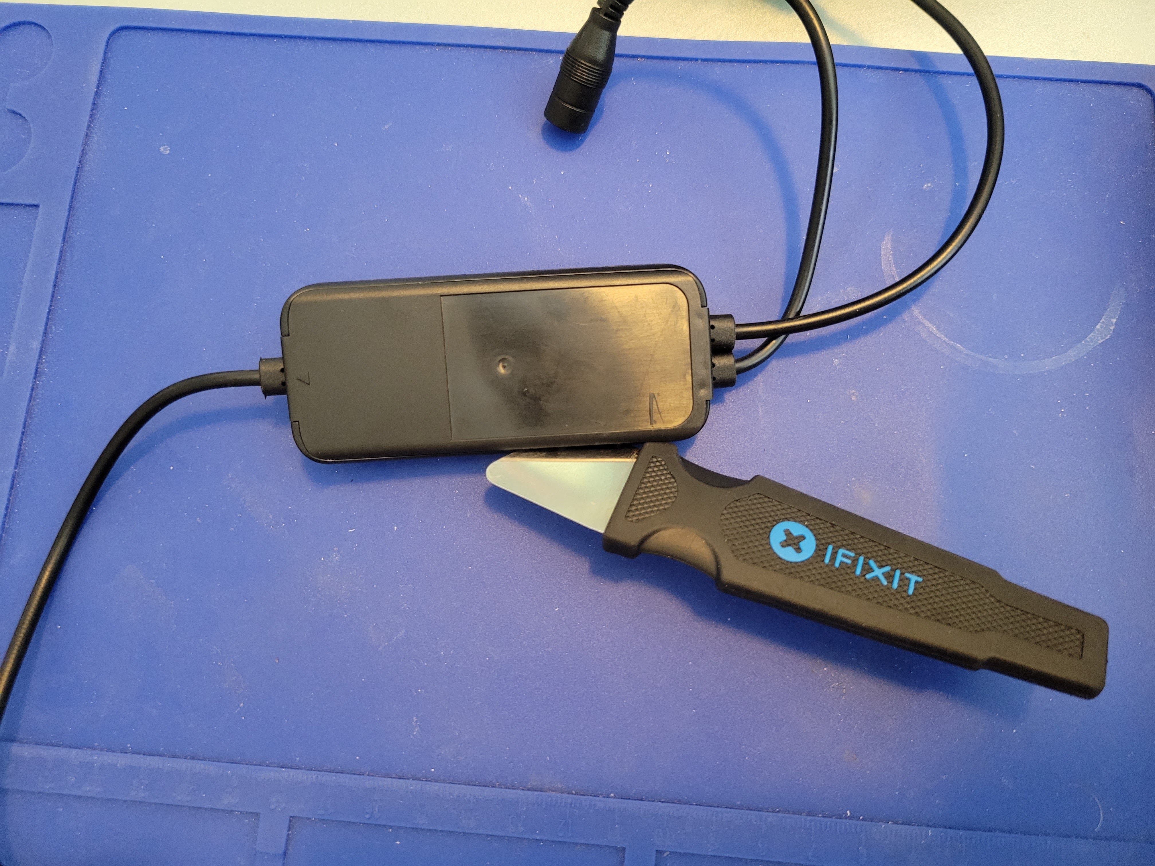
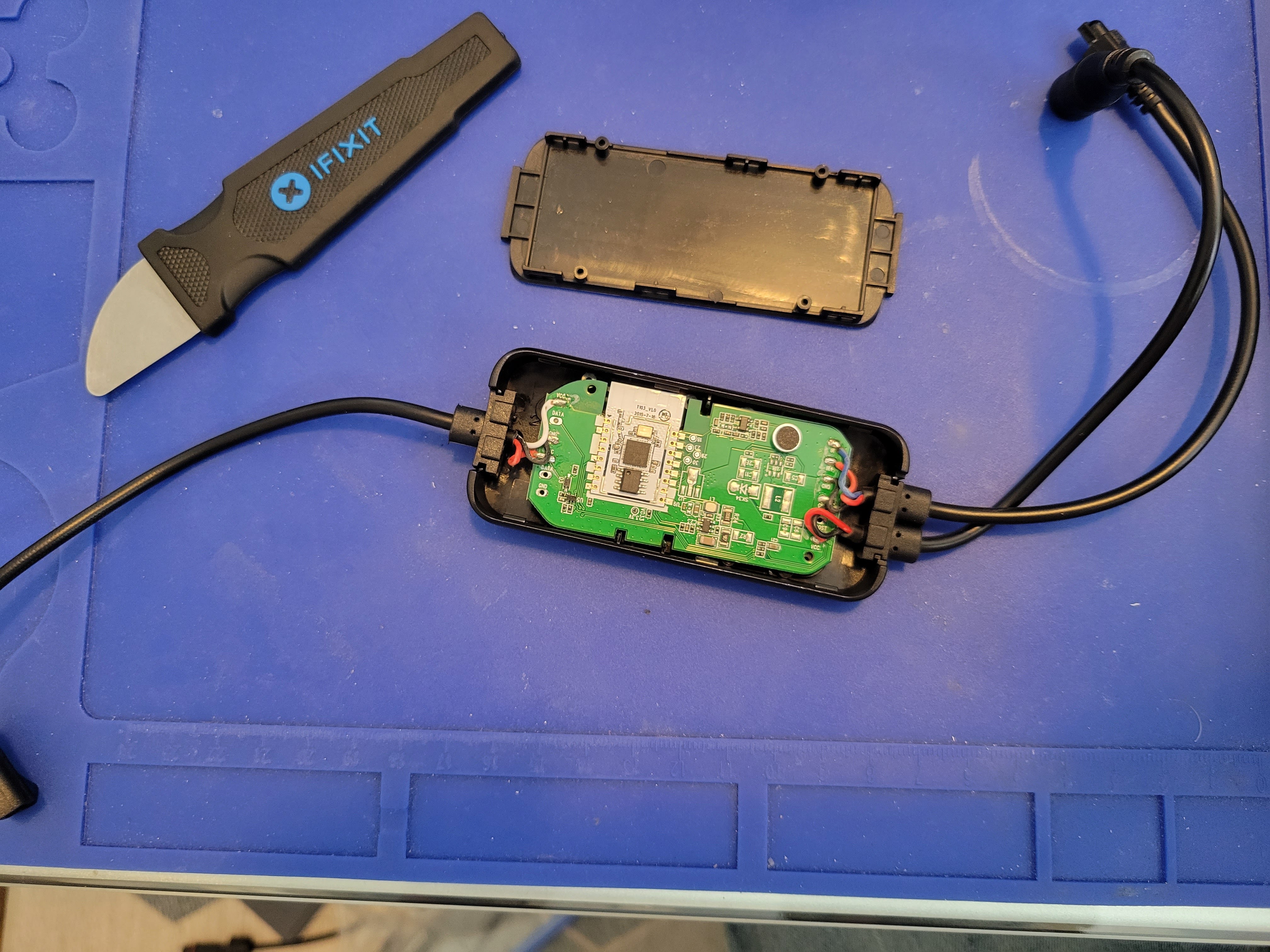
Desolder un-needed components
Add Leaded Solder
Get some leaded solder and melt some on the existing pins of the Realtek chip
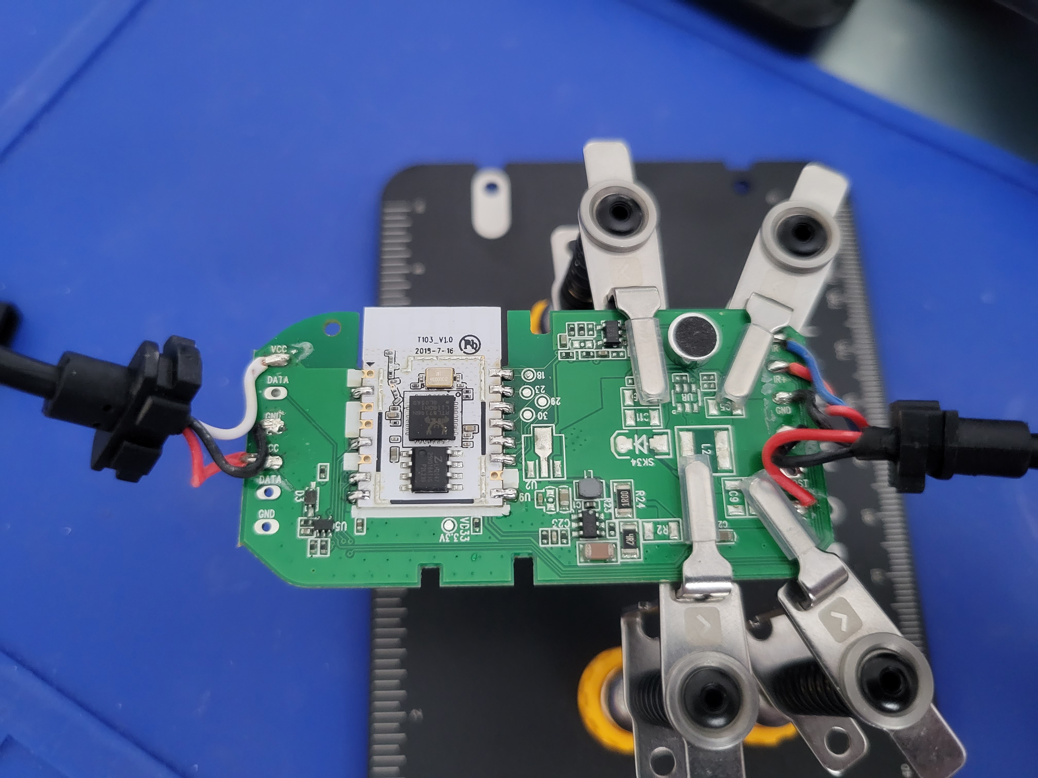
Heat em up! Pull em off! RAWHIDE!
Now use your hot air tool, soldering iron, or heat gun to remove the chips
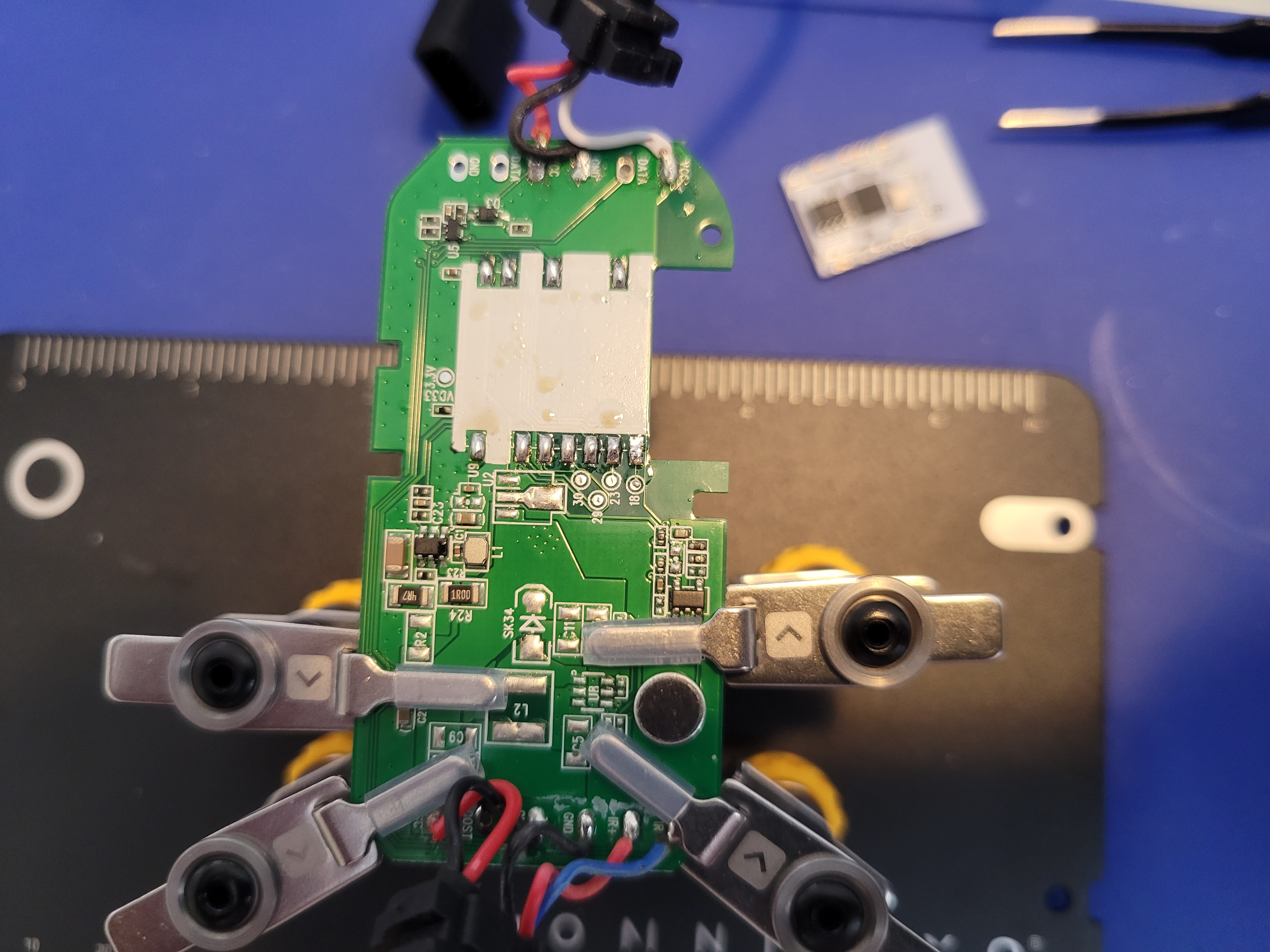
Solder new stuff
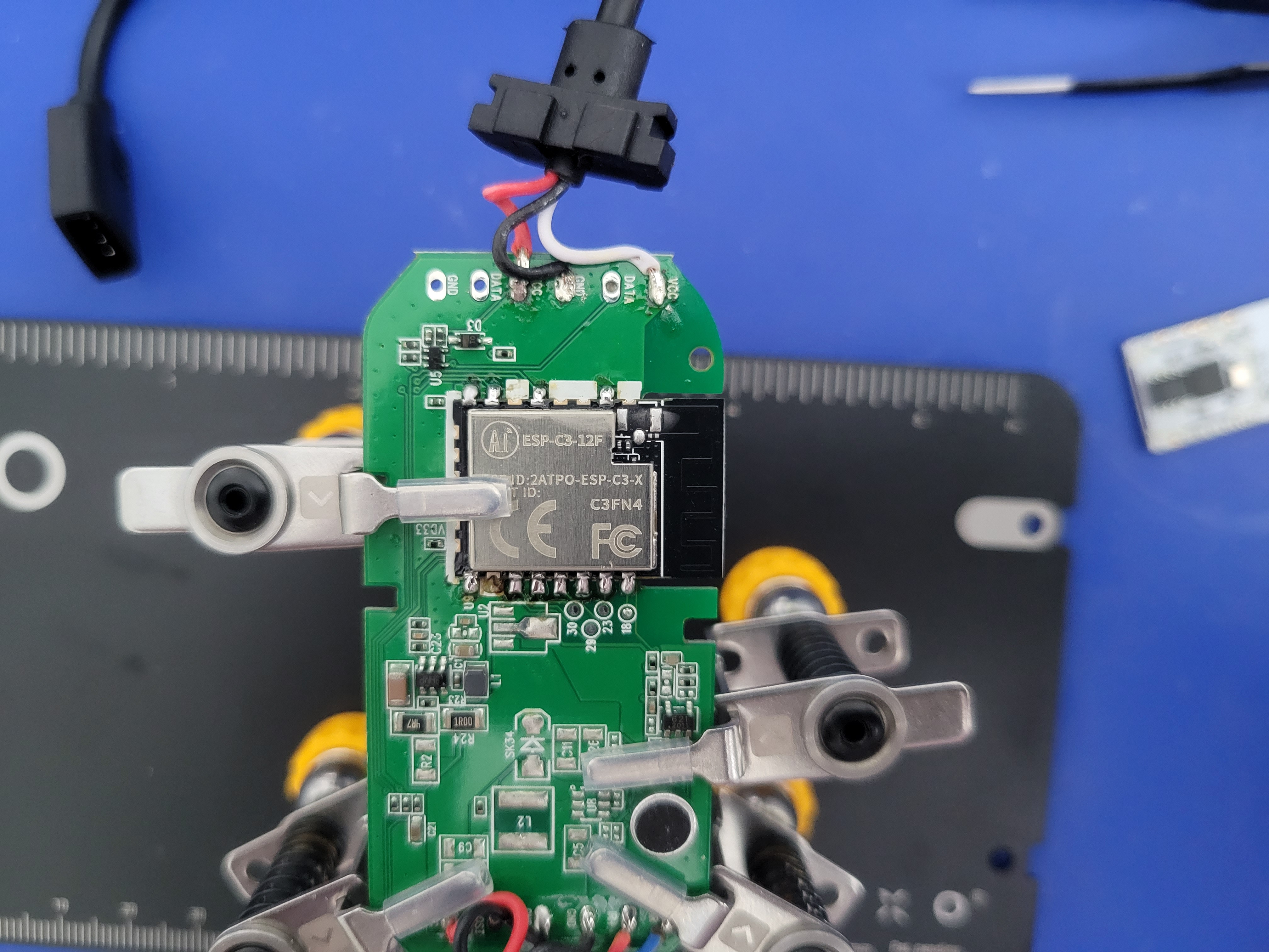
Now we want to solder the new chip back on
ESP32 C3 12F
Use some solder wick and clean up the pads where you pulled the Realtek chip from, this will allow the ESP32 C3 12F chip to sit flat on the PCB
Place the ESP32-C3-12F on the board and solder it into place
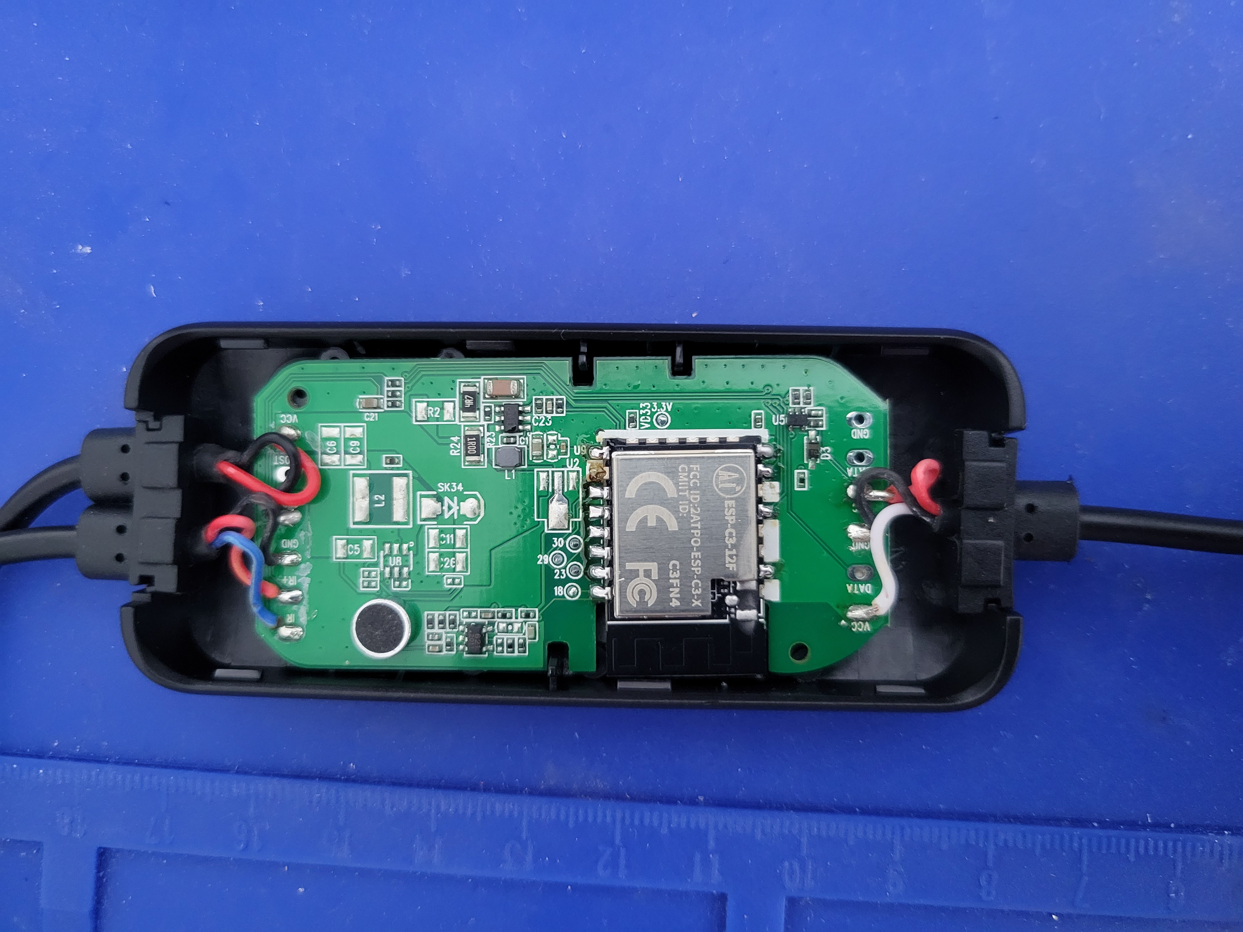
Reassemble the board back into the case
WLED Settings
General
| Location | Setting | Value | Description |
|---|---|---|---|
| /settings/leds? | Maximum Current | 3000 mA | The power supply provided can do up to 3 amps |
| /settings/leds? | LED Voltage | 12V | These are 12 Volt LEDs |
| /settings/leds? | LED1 Type | WS281x | Main lamp LED type |
| /settings/leds? | LED1 Color Order | BRG | Main lamp LED color order |
| /settings/leds? | LED1 Length | 48 | Main lamp LED count on the face of the lamp |
| /settings/leds? | LED1 GPIO | 21 | Main lamp LED GPIO pin |
| /settings/leds? | Button 0 GPIO | 19 | Button 0 GPIO pin |
| /settings/leds? | Button 1 GPIO | 18 | Button 1 GPIO pin |
| /settings/leds? | Button 2 GPIO | 5 | Button 2 GPIO pin |
| /settings/leds? | IR GPIO | 3 | Pick your remote type if you have one the lamp comes with the receiver but no remote |
3D Printable wall mount
Huge thanks to oldcrazyeye for the wonderful model: