Tasmota DevGroups Wiring Diagrams
We want the smart bulb to always have power allowing full control through home automation software and wall switches. Adds functionality without having to teach yourself and house guests how to turn a light on and off.
digiblurDIY Video
TASMOTA Device Groups allow multiple tasmota devices to sync changes to each other. Click your light switch and it sends off or on to the members of the device group.
Push the dimmer down on a dimmer light switch and have the smart bulbs dim as well. This page won't go into how awesome devgroups are but just shows how to wire things up physically to allow the software to sing.
Quick Primer
Need a quick example that you can see for yourself? Find two TASMOTA devices in your home to test with. 2 Smart Plugs, 2 Switches, or whatever combo you can find that have at least one relay or light to them. The full TASMOTA standard release build is necessary on each device. Go to the webpage GUI of each device and do the following on BOTH devices; go to the console, enter in devgroupname1 testgroup and hit Enter.
Once the device reboots, enter in SetOption85 1 on both devices.
Once they reboot, enter in devgroupshare without any value to verify it is set to {"DevGroupShare":{"In":"FFFFFFFF","Out":"FFFFFFFF"}}. This means send all changes and receive all changes.
Now toggle the relay/light on one of the devices. It should make the other device sync up to the other and vice versa. To disable this test just set SetOption85 0 to each device.
See the Devgroups Wiki Page, video above, and our wiring diagrams below for more info.
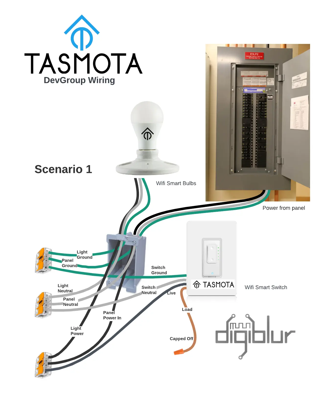
Single switch
Scenario 1
In this scenario there is a single pole switch that we don't want to have the relay turn off and on the lights. We want the smart bulb to always have power and through software tell it to turn off and on.
We have one wifi smart switch or dimmer running tasmota and one wifi smart bulb running tasmota using devgroups to control each other.

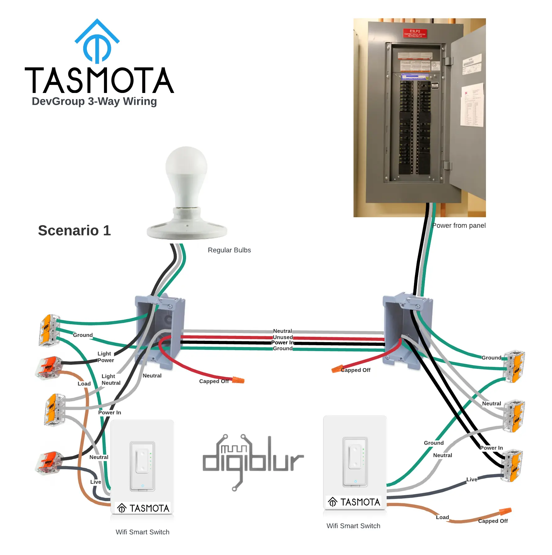
3-Way method with single pole / dimmer switches
There are times we don't need to use a full three way switch to have three way functionality. We can use the software to emulate a 3 way setup and using tasmota devgroups
Scenario 1
In this scenario we want to allow single pole switches or dimmers control standard bulbs in a three way configuration. Because we are using single pole switches we won't need to use all the traveler wires that a typical hard wired three way switch requires and so we will cap one of the traveler wires off in each box. In this scenario one of the switches will actually use it's relay to turn power off and on to the standard light bulbs.

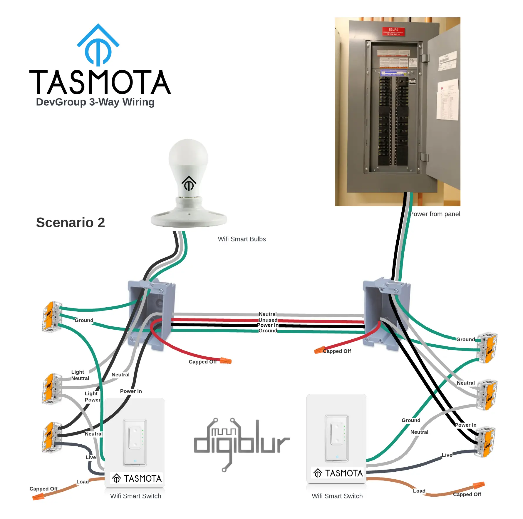
Scenario 2
In this scenario we want to allow single pole switches or dimmers control wifi smart bulbs running Tasmota in a three way configuration. Because we are using single pole switches we won't need to use all the traveler wires that a typical hard wired three way switch requires and so we will cap one of the traveler wires off in each box.
We will want to give continous power to the light bulbs and turn them off and on with software. Because the switches / dimmers won't need to use their relays to power off and on the lights they will just use devgroups to keep in sync with the bulbs.

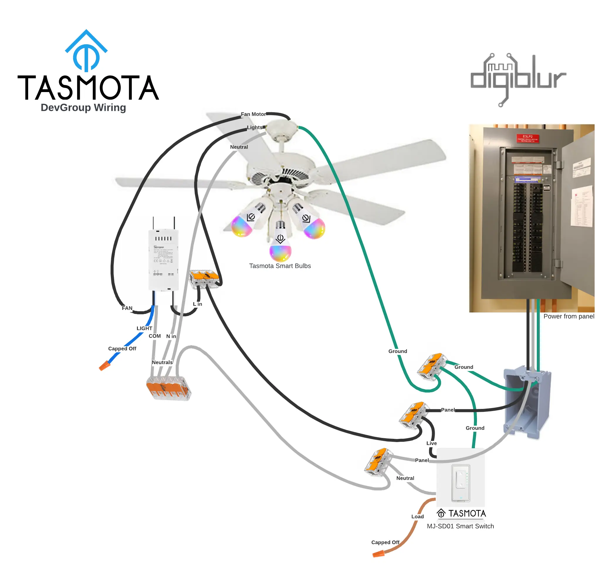
Sonoff iFan03/iFan04 with Smart Bulbs
In this scenario there is a single pole dimmer switch that we don't want to control the lights or fan. Instead we'll utilize it's buttons to control the remote smart fan controller (IFAN03) and smart bulbs both running Tasmota. The iFan04 is the same product as the iFan03 except the change to accomodate US 120V fans. We will want to give continous power to the light bulbs and turn them off and on with software. Because the dimmer fan controller won't need to use their relays to power off and on the lights they will just use devgroups to keep in sync with the bulbs. The output of the dimmer switch will be capped off and the output of the IFAN03 for lights will be capped off.
