
Check out these two videos we did on Zigbee fundamentals - Video #1 - Video #2 

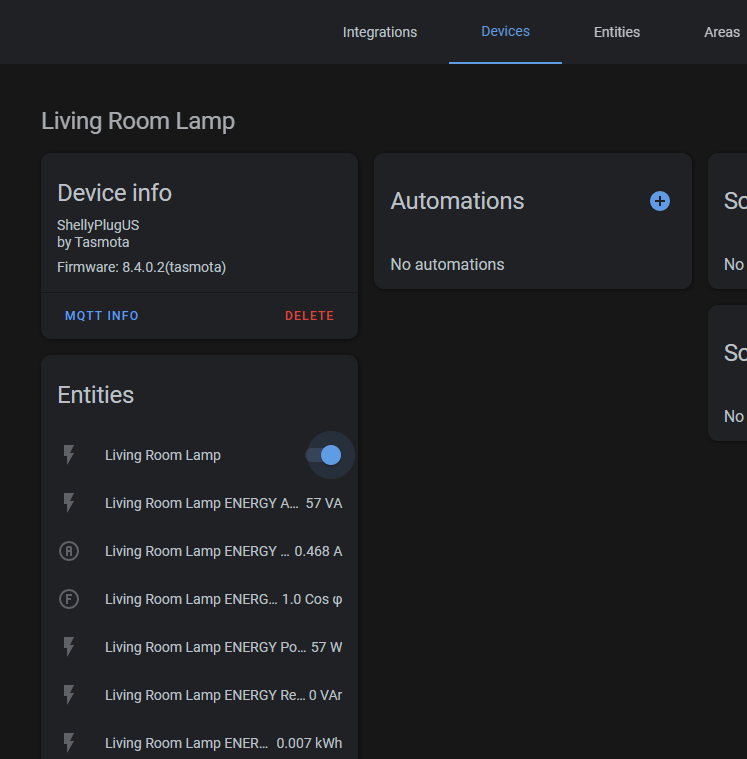
I reviewed the Sonoff Zigbee Bridge a few months ago in a video and was excited to see it had an ESP82xx chipset onboard.  This meant there was a glimmer of hope it could be flashed with open source local control firmware such as Tasmota!  That time has come!  The genius developers with Tasmota have done their magic again.  An inexpensive device you can add to Home Assistant as a Zigbee controller.  No YAML, no custom plugins, no MQTT.  One of the major advantages is being able to place it closer to your Zigbee devices which is especially helpful if you have your Home Assistant box in the basement or buried back in some closet.  Behold the ZHA Integration below.

UPDATE March 2021:  iTead also is now selling their USB 3.0 dongle that uses the same chip as the Zigbee Bridge.  It is preflashed with correct firmware out of the box that can also be used with ZHA and Zigbee2MQTT using the same procedure as below with the USB port. See more here in this article for Z2M usage https://www.digiblur.com/2021/03/zigbee2mqtt-with-sonoff-zigbee-bridge.html

Purchase Sonoff Zigbee Bridge:

Pre-Flashed with Tasmota - SKIP this Guide (Ebay)

Pre-Flashed with Tasmota from Cloudfree - SKIP this Guide

Banggood

iTead

Amazon

So how do we flash this?  First and foremost, there's NO soldering; don't close the window just yet!  It's relatively easy to do.  This is a full step by step walk through, some of the Tasmota veterans can skip many of the steps such as adding Tasmota to your WiFi network. 

During this process we will need a few pieces of software and files to flash things.  We are using Windows 10 during this process, feel free to grab the alternative versions if you are using Linux, Mac, etc.  

#1 Tasmotizer - Downloads the firmware and flashes the Bridge.  Some users have reported Tasmotizer does not work on their setup, as an alternative you can use NodeMCU Py-Flasher and manually download the tasmota-zbbridge.bin, please make sure you use the DOUT flashing method with this app. 

Download the latest "OTA file" for the Zigbee Bridge chipset

https://github.com/arendst/Tasmota/tree/development/tools

Use the latest ncp-uart-sw-x.x.x_115200.ota file (as of 2020/01/25 ncp-uart-sw-6.7.8_115200.ota is recommended). Utilize the "Download" button on GitHub.  Do not right click and save as! This could will result in a HTML file being downloaded instead of the actual file.

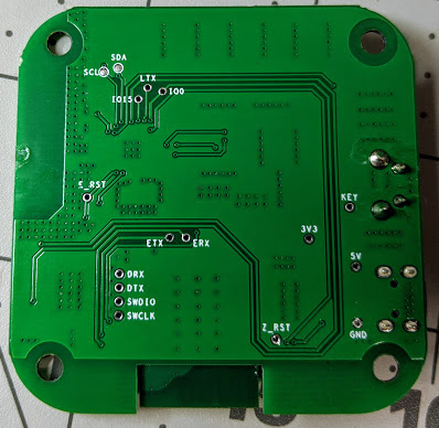
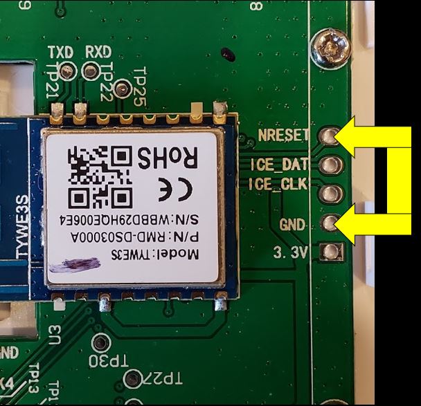
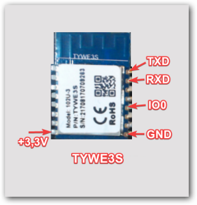
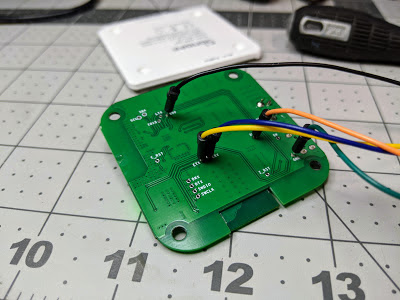
#2 Turn the Zigbee Bridge over and open it, there are four small Phillips screws on the bottom under the feet pads.  There are no wires or anything inside, just a simple PCB in a case.  Turn over the board and you'll notice they labeled all the via holes for us.  

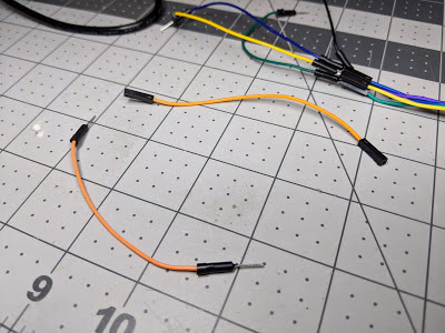
For ease of flashing I use typical breadboard jumpers inserted into female to female dupont jumpers attached to the USB TTL adapter as dupont male jumpers are usually too large.  Please remember to set your USB TTL adapter to 3v3 and NOT 5v.   If you do not have any breadboard jumpers, be creative, I've people use CAT5e wires too.

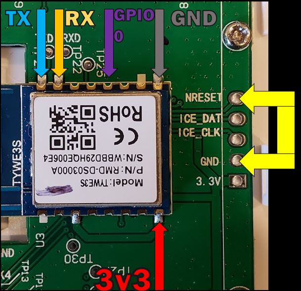
Attach the jumpers from the Zigbee bridge to the USB TTL (Amazon) or CH340G or (Aliexpress) as follows; (do NOT force them in the holes as this will damage the board, the jumper should be small enough to fit in the hole without the use of any force)

ETX to RX   (Note the RX to TX and TX to RX)

ERX to TX

3V3 to 3V3

GND to GND

IO0(GPIO Zero) to GND
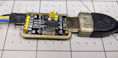
Example USB TTL

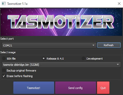
#3 Plug in the USB TTL to your computer and open Tasmotizer (run as administrator might be required if it crashes).  In the odd case of your antivirus notifying you, it's a false positive.  Choose your com port for the USB TTL flasher.  Select the Release radio button and choose tasmota-zbbridge.bin as shown below. 

Press Tasmotize! and it should start the flashing process.  If not check your connections and COM port and try again.  If the flash is still not successful, try applying ground to the Z_RST pad during the flashing process, this will force the Zigbee chipset to be quiet during the process.

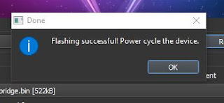
Once the flashing is complete, unplug the USB TTL flasher, remove the wires from the Zigbee bridge, and power it back up via the normal USB power connector using a proper 1A or more power supply.  You can also put it back in the case if needed. 

#4 Using your phone or computer, scan for available access points and look for a Tasmota-xxxx WiFi access point.

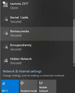
Connect to the AP and browse to 192.168.4.1 

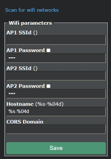
Click "Scan for wifi networks".  Select your network, enter the AP1 Password, select the check box next to it to verify you typed it correctly, then hit Save.  The bridge will reboot and attach to your WiFi network.  

#5 You will need to consult your router/dhcp server to determine the IP address of the new device.  Browse to this new IP address.

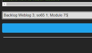
Click Console and paste in the following command on one line and hit enter:

Backlog Weblog 3; so65 1; Module 75

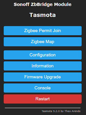
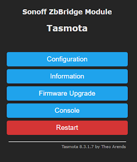
Tasmota will restart after a few seconds, once the reboot is complete, click Main Menu.

To verify the process flashes, it is recommended to open a second window with the Tasmota Console on it and use another window to flash the Zigbee chipset firmware. Click Firmware Upgrade, in the "Upgrade by file upload" box use the browse button and select the ncp-uart-sw ota file downloaded previously. 

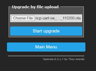
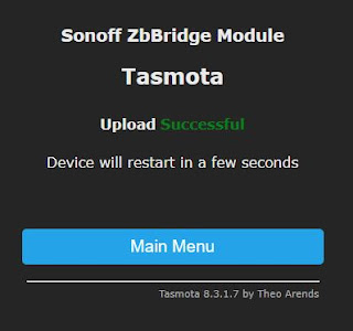
Press Start upgrade.  This will instruct Tasmota to flash the Zigbee chipset on the bridge that is necessary to integrate with the Zigbee Home Assistant integration.

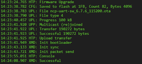
The file will be flashing in the background.  Do not restart or power cycle the device!  You can click Main Menu, then click Console to see the process. Note the XMD: commands, as Tasmota is pushing the OTA file via Xmodem to the Zigbee chipset automatically for you.  

If you do not see this XMD: Successful message, do not continue on past this point as the ZHA process will not work.  Try pushing the OTA file upload through the above process again.  Please verify there are no wires attached to the RX/TX pins and the bridge is powered through the bridge USB port with a proper USB cable and power supply.  A couple things you can try if you continue to receive have issue: change the power supply and change the power cable.  

Once the process is complete Tasmota will reboot and attempt to start Tasmota Zigbee. 

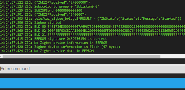
If you do not see the Tasmota Zigbee message of Zigbee started in the console do not continue past this point as this means the Zigbee chipset did not flash properly!  A couple things you can try if you continue to have this issue: change the power supply and change the power cable.  A last ditch effort if you still can't get the Zigbee chipset to flash is to update the bridge to the last developer version of Tasmota.  

#6 Issue the following command on the console to map the Zigbee chip to TCP Server Port 8888:

backlog rule1 on system#boot do TCPStart 8888 endon ; rule1 1 ; template {"NAME":"Sonoff ZHABridge","GPIO":[56,208,0,209,59,58,0,0,0,0,0,0,17],"FLAG":0,"BASE":18} ; module 0

Once the console reboots you should see the server has started on Port 8888:

17:35:58 TCP: Starting TCP server on port 8888
17:35:58 RSL: stat/tasmota/7FC5B0/RESULT = {"TCPStart":"Done"}

Last but not least, while we are here, let's set the update URL to the Zigbee Bridge variant.  This will prevent your future self from breaking your ZHA integration with an upgrade of the wrong bin file.  Enter the following on the Tasmota console.

otaurl http://ota.tasmota.com/tasmota/tasmota-zbbridge.bin.gz

We are done with Tasmota!  Let's jump into Home Assistant.

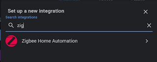
#7 Go to Configuration, Integrations, hit the Plus to add a new integration.  Select Zigbee Home Automation.

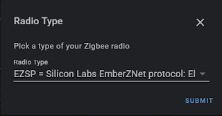
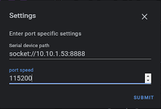
Choose "Enter Manually" and hit Submit.
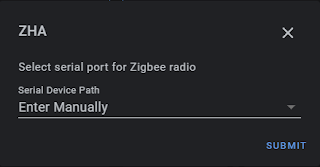
Radio Type is EZSP

Enter socket://<your bridge IP>:8888 and use 115200 for the port speed.  Hit submit.

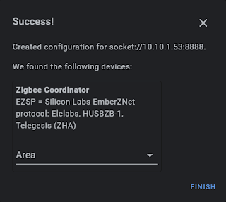
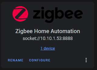
Give it a few seconds to query the device and you should see the following screen.

Congratulations!  You did it!  Hit Finish.  You should now have a Zigbee integration in Home Assistant.  Click Configure.

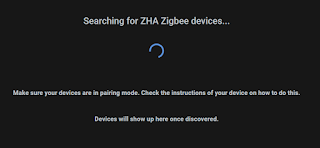
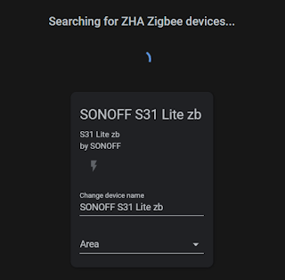
Hit the Plus and start pairing your various Zigbee devices.  

)

You are all done! Add all your various Zigbee device types and enjoy! We will continue to update this guide as things get shorter with the process to flash the device.  Be sure to stop in, read the process of the reverse engineering this device and thank the developers of Tasmota.  

Be sure to check us out on YouTube and Discord if you have any questions.  

Sonoff Zigbee Products

Zigbee Bridge(Amazon US)

Zigbee Bridge(iTead) - Zigbee Bridge(Banggood) 

Pre-Flashed with Tasmota - SKIP this Guide (Ebay)

Pre-Flashed with Tasmota from Cloudfree - SKIP this Guide

Zigbee Mini Switch

Zigbee Switch

Zigbee Temperature and Humidity Sensor

Zigbee PIR Motion Sensor(Junk!)

Zigbee Door/Window Sensor

Products We Use/Recommend

Amazon US - https://amzn.to/2YZNDeO

Amazon UK - https://amzn.to/3gVLiFZ

Amazon CA - https://amzn.to/2HchPZe

Discord Chat - https://discord.gg/bNtTF2v

Patreon -  https://www.patreon.com/digiblurDIY

Links to products provided by the ShareASale and Amazon Affiliate program.

If I you have an easy to open device with the TYWE3S module or simply open via/pin headers please be sure to share it in the comments below, email digiblurDIY on the Gmail domain, or send it via Discord (link below).  I'll update this post with various pictures and setup information as things progress below.

Take your stuff out the cloud and make it yours!  You paid for it, don't let someone else control it or possibly steal/spy on your data.  Tuya-Convert blocking have you locked into the cloud?  Let's check out the Tuya / Smartlife Flashing Jig.  You'll definitely be doing a dance of some sort after flashing Tasmota or ESPHome to your devices containing the TYWE3S module.  

Jig Pogo Pins

USB Flasher (FTDI)  or others

Jumper Wires

Test Probes or others 

2 inch Clamp(optional)

Fan/Dimmer Combo mentioned

If you are looking for a jig to be printed please message me on Discord - https://discord.gg/bNtTF2v

Resources

How to Use/Configure Tasmota - https://youtu.be/KOg5qwO3Rh4

Jig 3D Priint File - https://www.thingiverse.com/thing:4099748

Fan Module Blog Post - https://www.digiblur.com/2020/07/the-tasmota-fan-controller-ive-been.html

Esptool.py install - https://github.com/espressif/esptool

Tasmotizer - https://github.com/tasmota/tasmotizer

NodeMCU-Pyflasher - https://github.com/marcelstoer/nodemcu-pyflasher

Esphome - https://esphome.io/

Tasmota - https://tasmota.github.io/docs/

Products We Use/Recommend

Amazon US - https://amzn.to/2YZNDeO

Amazon UK - https://amzn.to/3gVLiFZ

Amazon CA - https://amzn.to/2HchPZe

Come chat with us!

Discord - https://discord.gg/bNtTF2v

Patreon - https://www.patreon.com/digiblurDIY

**

TYWE3S or Open Pin Header Devices

**

TreatLife Fan Speed Controller / Light Dimmer Combo - Setup Instructions

UPDATE 07/16/2020 - Video showing using the jig to flash this controller

Esmlfe/Treatlife DS03 Fan Controller and Light Dimmer

I've done several projects with the Sonoff iFan03 and various Martin Jerry dimmers to make my own fan controllers that work via Home Assistant while also following my rule of "never removing functionality while adding functionality" in a smart home.  The setup is challenging with replacing fan capacitors for 120vac based fans, dimmer rules, iFan rules, etc.  I've always been looking for a drop in fan controller that was not Zwave or Zigbee based.  Treatlife finally came out with a device that answers all of this and more!  

The Treatlife/Esmlfe 2 in 1 Fan Controller and Light Dimmer is currently priced comparatively with other Zwave fan controllers that only have fan controls.  Available on Amazon

A live stream is available showing the device -  View Live Stream on digiblurDIY

The switch will work with the Tuya Smartlife cloud app if you want to ride dangerously but as of this article if you attempt to use it via the Home Assistant Tuya integration, the dimmer and fan control entities will not show up.  So how do we control it?  We flash it with Tasmota of course!  Keep it all local control without the cloud! Unfortunately, at this time these devices are shipping with Tuya firmware that is blocking the current TuyaConvert exploit.  The switch will need to be flashed via the old school manual method.  Don't worry, this is fairly simple.  

Disconnect any power going to the device!  Remove the 4 screws and the face plate will come off.  There are no ribbon cables or wires to worry about.

The TYWE3S module containing the flash-able ESP8266 chip is wide out in the open.  There are multiple choices you can use to flash this chip with the 3v3 and GND headers.  Using a TTL USB adapter, you need to connect the following wires:  3v3 (do not use 5 volts!), Ground, RX, and TX.  GPIO 0 will also need to be attached to ground to enable flash mode on an ESP8266.  Instead of soldering, if you have a 3D printer you can also make a pogo pin jig as shown here and below.  Remember that RX goes TX and TX goes to RX on the USB TTL adapter.

Also, note you will need to put a jumper between NRESET and GND locations. This keeps the secondary TuyaMCU in a reset loop during the flashing of Tasmota.  Without this jumper the flashing process will not work.  

Once you've connected the necessary wires to your USB TTL device you can utilize Tasmotizer to flash the chip.  Additional information available on flashing Tuya devices can be found here in the Tasmota Wiki  

Once flashed, disconnect GPIO 0 so it will boot up into Tasmota.  You need to scan the WiFi access points with a phone, laptop, or tablet.  You should see a tasmota-xxxx or similar named WiFi access point.  Connect to this AP, accept any messages about no internet connectivity if your device prompts you, this is normal.  Browse to 192.168.4.1 if it does not open the Tasmota page automatically. Click scan, select your home WiFi network and enter the password for your network.  Check the box show password to make sure you have the password correct.  Save the settings.  The Fan controller should now be on your network.  You can look on your router or WiFi attached devices and find the IP address of the device.  Browse to this IP address to complete the rest of the Tasmota setup.

It's all down hill after this...  click the Console button on the Tasmota GUI of the fan switch.  Issue the following commands.  Take note it will restart during many of the commands, wait for the console to somewhat settle down before issuing the next one.  

module 54

backlog so97 1 ; tuyamcu 11,1 ; tuyamcu 12,9 ; tuyamcu 21,10

backlog ledtable 0 ; dimmerrange 10,1000 ; so59 1 ; so68 0

There is a configuration choice to decide; by default the fan speed can be changed while the fan is off and it will not turn on.  This can be a good or bad thing depending on your choices.  Pick the Rule Set you like (you can change it later by simply copy and pasting the rule back into the console)

Add the following rule, this should be all on ONE line in the Tasmota Console on the Switch.

(SELECT ONE)

OPTION A: Does NOT turn the fan on when the speed/preset is changed:

Rule1 on TuyaReceived#Data=55AA03070005030400010016 do publish2 stat/%topic%/speed 3,0 endon

on TuyaReceived#Data=55AA03070005030400010117 do publish2 stat/%topic%/speed 3,1 endon

on TuyaReceived#Data=55AA03070005030400010218 do publish2 stat/%topic%/speed 3,2 endon

on TuyaReceived#Data=55AA03070005030400010319 do publish2 stat/%topic%/speed 3,3 endon

OPTION B: The fan turns on when the speed/preset is changed:

Rule1 on TuyaReceived#Data=55AA03070005030400010016 do backlog power1 1 ; publish2 stat/%topic%/speed 3,0 endon on TuyaReceived#Data=55AA03070005030400010117 do backlog power1 1 ; publish2 stat/%topic%/speed 3,1 endon on TuyaReceived#Data=55AA03070005030400010218 do backlog power1 1 ; publish2 stat/%topic%/speed 3,2 endon on TuyaReceived#Data=55AA03070005030400010319 do backlog power1 1 ; publish2 stat/%topic%/speed 3,3 endon

Enable the rule with the following

Rule1 1

You can then add the necessary MQTT configuration, device name, etc and it should be safe to disconnect the wires, reassemble the switch and install it on the wall, on mains AC power to the fan.  You might be asking at this point "how do I control the fan speed from the GUI?"  You will need to utilize the following commands to send the fan speeds on the console

TuyaSend4 3,0  (fan speed 1)

TuyaSend4 3,1  (fan speed 2)

TuyaSend4 3,2  (fan speed 3)

TuyaSend4 3,3  (fan speed 4)

You can also send those over MQTT if you like from various automations using cmnd/topic/tuyasend4 with a payload of 3,0 , etc.  

Home Assistant Configuration

If you already have a "fan" and "light" section do not duplicate these sections in your Configuration YAML file.  Don't forget to change the "yourtopic" topic to the MQTT topic configured in your fan switch MQTT page of Tasmota from the previous steps

As of 2021.4 Home Assistant MQTT Fan has changed (thanks to @merdely for the help):

fan:
  - platform: mqtt
    name: "Your Fan"
    qos: 1
    state\_topic: "stat/yourtopic/POWER1"
    command\_topic: "cmnd/yourtopic/POWER1"
    availability\_topic: "tele/yourtopic/LWT"
    percentage\_state\_topic: "stat/yourtopic/speed"
    percentage\_value\_template: '{{ ((value | replace("3,","")) | int + 1) \* 25 }}'
    percentage\_command\_topic: "cmnd/yourtopic/tuyasend4"
    percentage\_command\_template: "3,{{ ((value | int - 1) / 25) | int }}"
    preset\_mode\_state\_topic: "stat/yourtopic/speed"
    preset\_mode\_value\_template: '{{ value | replace("3,0", "turtle") | replace("3,1", "low") | replace("3,2", "medium") | replace("3,3", "high") }}'
    preset\_mode\_command\_topic: "cmnd/yourtopic/tuyasend4"
    preset\_mode\_command\_template: '{{ value | replace("turtle", "3,0") | replace("low", "3,1") | replace("medium", "3,2") | replace("high", "3,3") }}'
    preset\_modes:
      - "turtle"
      - "low"
      - "medium"
      - "high"
    payload\_available: "Online"
    payload\_not\_available: "Offline"
    payload\_on: "ON"
    payload\_off: "OFF"

light:
  - platform: mqtt
    name: "Your Light"
    state\_topic: "tele/yourtopic/STATE"
    state\_value\_template: "{{ value\_json.POWER2 }}"
    command\_topic: "cmnd/yourtopic/POWER2"
    availability\_topic: "tele/yourtopic/LWT"
    brightness\_state\_topic: "tele/yourtopic/STATE"
    brightness\_command\_topic: "cmnd/yourtopic/Dimmer"
    brightness\_scale: 100
    brightness\_value\_template: "{{ value\_json.Dimmer }}"
    payload\_on: "ON"
    payload\_off: "OFF"
    payload\_available: "Online"
    payload\_not\_available: "Offline"

Old Configuration for HA 2021.3 and earlier kept for documentation purposes

fan:
  - platform: mqtt
    name: "Bedroom Fan"
    state\_topic: "stat/treatfan/POWER1"
    command\_topic: "cmnd/treatfan/POWER1"
    speed\_state\_topic: "stat/treatfan/speed"
    speed\_command\_topic: "cmnd/treatfan/tuyasend4"
    availability\_topic: "tele/treatfan/LWT"
payload\_available: "Online"
    payload\_not\_available: "Offline"    
    payload\_on: "ON"
    payload\_off: "OFF"
    payload\_low\_speed: "3,1"
    payload\_medium\_speed: "3,2"
    payload\_high\_speed: "3,3"
    speeds:
- low
      - medium
      - high

light:
  - platform: mqtt
    name: "Bedroom Light"
    state\_topic: "tele/treatfan/STATE"
    state\_value\_template: "{{ value\_json.POWER2 }}"
    command\_topic: "cmnd/treatfan/POWER2"
    availability\_topic: "tele/treatfan/LWT"
    brightness\_state\_topic: "tele/treatfan/STATE"
    brightness\_command\_topic: "cmnd/treatfan/Dimmer"
    brightness\_scale: 100
    brightness\_value\_template: "{{ value\_json.Dimmer }}"
    payload\_on: "ON"
    payload\_off: "OFF"
    payload\_available: "Online"
    payload\_not\_available: "Offline"

That's it!  Enjoy!  If you need help feel free to pop into Discord and ask for a hand.  

Treatlife/Esmlfe 2 in 1 Fan Controller and Light Dimmer

Discord - https://discord.gg/bNtTF2v

Patreon - https://www.patreon.com/digiblurDIY

YouTube Channel - https://www.youtube.com/digiblurDIY

Links to products provided through the Amazon Affiliate program.

UPDATE: The Shelly1 process shown in this video is the easy no solder method.  

Video

We added a bit of DIY automation to the garage door for minimal costs and of course without any fees or forced cloud control  Taking a deep dive for the new folks to the DIY Garage scene and for the semi-DIY'ers we also show some other easy solutions.

Parts

Sonoff SV

Sonoff SV (Direct from iTead)

Reed Switch for Open/Close Sensor

Alternate Reed Switch

Moes Garage Door Opener (not a recommended choice unless you like this hardware)  Shelly1 or Sonoff SV is my recommendation

Wyze Sensor Setup Video

Moes Garage Door Opener Setup Post

Tasmotizer Download

Tasmota Garage Setup & Rules (for easy copy and paste from the video)

ATTN Shelly1 Users! Use the Shelly1 Section at the bottom of this post for modified rules/commands (the below is for the Sonoff SV)

switchmode2 1

poweronstate 0

setoption0 0

pulsetime1 10

(This rule below should all be pasted at one time)

Rule1 on switch2#state=0 do publish2 stat/%topic%/status closed endon on switch2#state=1 do publish2 stat/%topic%/status open endon

Turn on the rule with this command:

Rule1 1

Sonoff SV - YAML Config

cover:

  - platform: mqtt

    name: "Garage Door"

    command_topic: "cmnd/GarageDoor/POWER"

    state_topic: "stat/GarageDoor/status"

    availability_topic: "tele/GarageDoor/LWT"

    qos: 1

    payload_available: "Online"

    payload_not_available: "Offline"

    payload_open: "ON"

    payload_close: "ON"

    payload_stop: "ON"

    state_open: "open"

    state_closed: "closed"

    device_class: garage

Change the MQTT Topic of "GarageDoor" in all three spots if  you use a different topic in the Tasmota MQTT Config

How to Utilize a Wireless Door/Window Sensor (Wyze, Zwave, Zigbee, 433mhz etc)

Setup the wireless sensor in Home Assistant and verify it is working.  The switch2 rule and setup of the wired reed sensor will not be needed in Tasmota.  You will still need the pulsetime1 command done to only make the relay toggle for the short period to simulate the garage door button push.  

Create an automation in Home Assistant either via the YAML editor or Automation GUI as follows.  Edit the binary_sensor and MQTT topic name as needed. This will push the state of the wireless sensor state changes into MQTT which Home Assistant will then read as an all in one sensor/relay from the Garage Door.  A small but quick loop around trick!  

YAML Method

- id: '15912322314808'
  alias: Reed2MQTT
  description: ''
  trigger:
  - entity_id: binary_sensor.wyzebenchreed
    platform: state
  action:
  - data:
      payload_template: "{{ states('binary_sensor.wyzebenchreed') }}"
      topic: stat/GarageDoor/status
    service: mqtt.publish

GUI Method

YAML Config for secondary reed sensor (small change to state payloads)

cover:

  - platform: mqtt

    name: "Garage Door"

    command_topic: "cmnd/GarageDoor/POWER"

    state_topic: "stat/GarageDoor/status"

    availability_topic: "tele/GarageDoor/LWT"

    qos: 1

    payload_available: "Online"

    payload_not_available: "Offline"

    payload_open: "ON"

    payload_close: "ON"

    payload_stop: "ON"

    state_open: "on"

    state_closed: "off"

    device_class: garage

Shelly 1 Tasmota Garage Setup & Rules

switchmode1 2

poweronstate 0

setoption0 0

pulsetime1 10

(This rule below should all be pasted at one time)

Rule1 on switch1#state=0 do publish2 stat/%topic%/status closed endon on switch1#state=1 do publish2 stat/%topic%/status open endon

Turn on the rule with this command:

Rule1 1

Shelly1 YAML Config

cover:

  - platform: mqtt

    name: "Garage Door"

    command_topic: "cmnd/GarageDoor/POWER"

    state_topic: "stat/GarageDoor/status"

    availability_topic: "tele/GarageDoor/LWT"

    qos: 1

    payload_available: "Online"

    payload_not_available: "Offline"

    payload_open: "ON"

    payload_close: "ON"

    payload_stop: "ON"

    state_open: "open"

    state_closed: "closed"

    device_class: garage

Can't see the little garage door being up or down in the Home Assistant GUI?  Create an easy to read binary sensor

Secondary Binary Sensor YAML Config

binary_sensor:

  - platform: mqtt

    name: "Garage Door State"

    state_topic: "stat/GarageDoor/status"

    payload_on: "open"

    payload_off: "closed"

    availability_topic: "tele/GarageDoor/LWT"

    payload_available: "Online"

    payload_not_available: "Offline"

    qos: 1

    device_class: opening  

-=-=-=-Products We Use/Recommend-=-=-=-

Amazon US - https://amzn.to/2YZNDeO

Amazon UK - https://amzn.to/2TnG2R4

Amazon CA - https://amzn.to/2HchPZe

-=-=-=-Come chat with us!-=-=-=-

Discord - https://discord.gg/bNtTF2v

Patreon - https://www.patreon.com/digiblurDIY

In an upcoming video on the DIY Smart Home series, we planned to "smartify" the garage door and, of course, it had to be local control without all the fees and ever changing nonsense and security issues that the cloud brings.  One option we picked up was using the Sonoff SV to try, but as an alternative the Moes version of the garage door opener is easy to install.  Out of the box it does come with Tuya/Smart Life firmware, but of course we wanted to get rid of that, and put open source local control software such as Tasmota on it. Moes Garage Door Opener on Amazon

At first glance you might be thinking that someone simply took a Sonoff basic, added a couple wires, and repackaged it; unfortunately that isn't true.  If it was as easy as a Sonoff Basic, we probably wouldn't be writing this article on how to get it to work with Tasmota.  It does have a Tuya module inside, and as of the writing of this article, Tuya-Convert does work on the device.  But before I was quick to convert it, I decided to pop it open and found that it was sporting a TuyaMCU onboard!  I had this funny feeling they were doing something odd and decided to do a bit of sniffing on the TuyaMCU RX/TX serial lines first, and I was glad I did!  So after a couple of Live Streams on YouTube of the process, and banging my head against the wall a bit, I present to you the rules necessary to set this little guy up.

Live Stream #1 & Live Stream #2 on YouTube

Flash the device with either soldering to the chip via USB TTL and Tasmotizer, or use Tuya-Convert.  Do the dance to get the device on your WiFi like you normally would, and browse to the Tasmota GUI using the local IP of the device found from your Router/DHCP Server.  As always upgrade to teh latest Tasmota by utilizing the Firmware Upgrade button in the GUI. Configure your MQTT Broker and Custom Topic like you normally would, then click the Console Button and paste these commands in one by one:

template {"NAME":"Moes Garage","GPIO":\[255,148,255,149,255,255,255,255,255,255,21,255,255\],"FLAG":15,"BASE":18}

module 0

At this point, the device should reboot. Now you might be thinking “Why don't we just use TuyaMCU built into Tasmota?”  The problem with that is during any reboot of the device, it was cycling the relay which could cause your garage door to open at 3 AM!  So we do it raw, plus add a few features!  Go back to the console of Tasmota, and enter these commands in (be careful to grab the entire rule due to word wrapping):

Rule1 on System#Boot do backlog baudrate 9600 ; serialsend5 55aa000300010407 ; serialsend5 55AA0008000007 ; ruletimer1 10 endon on rules#timer=1 do backlog serialsend5 55AA00000000FF ; ruletimer1 10 endon

Rule1 1

This rule sets up the serial communication at boot, sets the LED, sends a command to query the state of the reed switch (i.e., garage door position) in case it changed while the power was off, and then sets up the 10 second heartbeat packet the TuyaMCU requires.

Rule2 on event#doortoggle do serialsend5 55AA0006000501010001000D endon

Rule2 1

This creates an event that is sent from your home automation software (via MQTT) to toggle the relay which opens/closes the garage door.  OK, now for the last rule, and this all on one line!

Rule3 on SerialReceived#Data=55AA0307000565010001007555AA03070005010100010011 do power1 1 endon on SerialReceived#Data=55AA0307000501010001001155AA0307000807020004000000001E55AA03070005650100010075 do power1 1 endon on SerialReceived#Data=55AA0307000565010001017655AA03070005010100010112 do power1 0 endon on SerialReceived#Data=55AA0307000501010001011255AA0307000807020004000000001E55AA03070005650100010176 do power1 0 endon

Rule3 1

This rule watches the TuyaMCU packets for the garage door state (open or closed) via the magnetic reed switch attached to the door.  This rule toggles the fake relay on the Tasmota GUI and can be monitored via the power1 MQTT topic.

powerretain 1

Makes the state of the door being open or closed be retained during a Home Assistant reboot.

Restart the Garage Door Opener.  You can use the Restart button on the GUI of Tasmota.

View on Amazon - Moes Garage Door Opener

But wait . . . can't we do this without all these serial rules on Tasmota with a Sonoff SV?  Absolutely!  But you do have to remember this is an alternative solution that is ready to go in the case, without any wire soldering, 3D printed cases, etc.  Options for everyone, choose the one that best fits your needs.

Home Assistant Sample Configurations

Modify the “GarageDoor” topic below to match the unique topic set in the Tasmota MQTT Configuration:

cover:

  • platform: mqtt

    name: "Garage Door"

    command_topic: "cmnd/GarageDoor/event"

    state_topic: "stat/GarageDoor/POWER"

    availability_topic: "tele/GarageDoor/LWT"

    qos: 1

    payload_available: "Online"

    payload_not_available: "Offline"

    payload_open: "doortoggle"

    payload_close: "doortoggle"

    payload_stop: "doortoggle"

    state_open: "OFF"

    state_closed: "ON"

    device_class: garage

Swap the states of OFF/ON if your status is backwards depending on how the sensor is used/mounted.

Moes Garage Door Opener

Door Sensor and Wire

Accessories for Installation Included

Integrating a Switch into Home Assistant and Setting up the Long Press Action to toggle another switch in the DIY Smart Home.  Join us on this series when we tackle a new home and evolve it into an automated smart home. 

-=-=- Parts -=-=-
Martin Jerry Dimmer
Martin Jerry Switch
Cliff QuickTest
Wago221 Connectors

TuyaConvert Process - https://youtu.be/dt5-iZc4_qU

Home Assistant Install Guide - https://www.home-assistant.io/hassio/installation/

Products We Use/Recommend
Amazon US - https://amzn.to/2YZNDeO
Amazon UK - https://amzn.to/2TnG2R4
Amazon CA - https://amzn.to/2HchPZe

Come chat with us!
Discord - https://discord.gg/bNtTF2v
Patreon - https://www.patreon.com/digiblurDIY

Links to products provided through the Amazon Affiliate program.

So you want to create a Smart Home? Are you unsure what to do and what to get?  Join us on this series when we tackle a new home and evolve it into an automated home.  This episode we are installing and setting up Home Assistant on the Raspberry Pi 4, getting everything ready to install our light switches and automations.

Parts List
Raspberry Pi 4 https://amzn.to/2sNZjCg
Power Supply - https://amzn.to/2TO4Ofn
64gb Micro SD Card - https://amzn.to/2Rh4aFF
Fliirc Case - https://amzn.to/2QuUDKR
APC Battery Backup - https://amzn.to/2utcY21

Others
Martin Jerry Dimmer - https://amzn.to/2Thgun0
Martin Jerry Switch - https://amzn.to/2qowzv3
Lohas 4 pack - https://amzn.to/2Z4qiWd

Hassio Install Guide - https://www.home-assistant.io/hassio/installation/

MQTT Addon Sample Config (Post 105.x)

logins:
- username: diymqtt
password: mqttdiy
anonymous: false
customize:
active: false
folder: mosquitto
certfile: fullchain.pem
keyfile: privkey.pem
require_certificate: false

Products We Use/Recommend
Amazon US - https://amzn.to/2YZNDeO
Amazon UK - https://amzn.to/2TnG2R4
Amazon CA - https://amzn.to/2HchPZe

Come chat with us!
Discord - https://discord.gg/bNtTF2v
Patreon - https://www.patreon.com/digiblurDIY

Links to products provided through the Amazon Affiliate program.