Tasmota New Device Procedure
Can't get that newly flashed device to work with Tasmota? None of the built in modules apply to your device? Don't worry, the procedure to make a new template is relatively simple for most devices. The procedure is mainly a two step process; 1. Find the outputs such as relays that turn power on and off and the LED indicators. 2. Find the manual inputs to the device such as buttons and switches. Video of the process - https://youtu.be/eDoIkd58HRM
First begin this procedure by disabling power state saves. This is to prevent the case of a stuck device as each GPIO pin is queried. The SetOption36 verifies that the boot loop control is not disabled. Copy and paste the following into the Tasmota Console screen, this turns off saving the state of the relay in case one causes a bootloop:
Backlog SetOption0 0; SetOption36 1

Finding the Outputs
Next, for the ESP8266 (other templates below) assign Relay1-8 to the typical mainstream GPIO pins for our testing. This is done automatically by a simple copy and paste of the following to the Tasmota console:
ESP8266
backlog template {"NAME":"NewDevice1","GPIO":[0,0,0,224,225,226,0,0,227,228,229,230,231,0],"FLAG":0,"BASE":18} ; module 0
ESP32 (Normal Dual Core and Solo)
backlog template {"NAME":"ESP32_AllRelays","GPIO":[224,225,226,227,228,229,1,1,230,231,232,233,1,1,234,235,236,237,238,239,240,241,242,243,0,0,0,0,244,245,246,247,248,249,250,251],"FLAG":0,"BASE":1,"CMND":"SO0 0|SO65 0"} ; Delay 1; Module 0
ESP32-C3
backlog template {"NAME":"ESP32C3 ALL Relays","GPIO":[224,225,226,227,228,229,230,231,232,233,234,0,0,0,0,0,0,0,235,236,237,238],"FLAG":0,"BASE":1,"CMND":"SO0 0|SO65 0"} ; Delay 1 ; Module 0
ESP32-S2 (1st Batch of Relays)
backlog template {"NAME":"ESP32S2_AllRelays1","GPIO":[224,225,226,227,228,229,230,231,232,233,234,235,236,237,238,239,240,241,242,243,244,245,246,247,248,249,250,251,1,1,1,1,1,1,1,1],"FLAG":0,"BASE":1,"CMND":"SO0 0|SO65 0"} ; Module 0
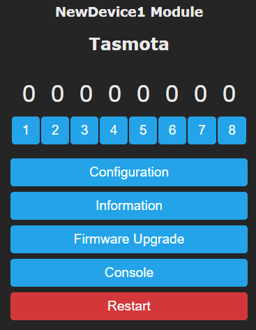
The device will reboot after this command is entered. Wait for the console to reload and return to the Tasmota main GUI page.
The virtual buttons 1-8(or more if using the ESP32) will now be displayed. Toggle each one on and off, listen for relays, and look for any LEDs changing on the device. If you see something change, take a note of it. For instance if the GUI button 2 toggles the relay. Make a note of GUI Button#4 = Relay. If GUI Button 7 toggles the blue LED, make a note of of GUI Button 7 = Blue Led.
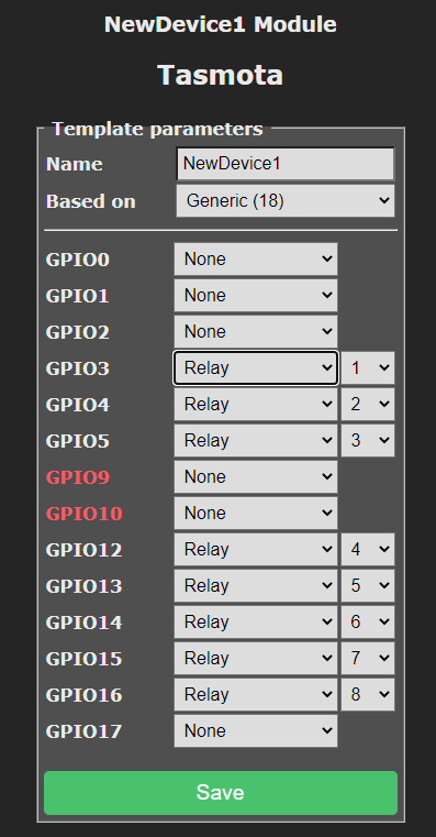
Once all 8 buttons are toggled they will need to be converted to the actual GPIO number. Go to Configuration->Configure Template. This screen will show which of the GUI Buttons (Relays) are attached to each GPIO number, basically a conversion chart. GUI Button#4 is actually called Relay 4 in Tasmota. Relay 4 is assigned to GPIO 12 in this example, change the note to GPIO 12 = Relay1. The Blue LED would convert to GPIO 15 = Blue LED.
If all of the relays and/or LEDs are not found yet, continue on with the second template below. Go back to the console and paste in this template command:
ESP8266
template {"NAME":"NewDevice2","GPIO":[224,225,226,0,0,0,0,0,0,0,0,0,0,0],"FLAG":0,"BASE":18}
ESP32S2 (Second Batch of Relays)
backlog template {"NAME":"ESP32S2_AllRelays2","GPIO":[0,0,0,0,0,0,0,0,0,0,0,0,0,0,0,0,0,0,0,0,0,0,0,0,0,0,0,0,224,225,226,227,228,229,230,231],"FLAG":0,"BASE":1,"CMND":"SO0 0|SO65 0"} ; Module 0
Repeat the same process for these 3(or more if using ESP32) buttons on the GUI. If none of the outputs are found on then device then a TuyaMCU most likely is in play or if this is a Smart Light, it could have a hardware LED driver.
Once all of the outputs are found, return to the Configure Template, and configure the Relays, LEDs, etc. This will eliminate the need to check these GPIO pins for inputs. One trick to clear this screen quickly, change the "Based On" drop down selection to something else then put it back to "Generic (18)". Based on the device you may need to configure them as inverted LEDs, Relays, etc., this will be indicated with a lower case "i". Smart bulbs will have each color channel configured as PWMx. The order will be in R, G, B, CW, WW. If multiple status LEDs are available, one consideration for ease of use is to assign one as Ledlink and the other as LED1.
Finding the Inputs
If the device does not have any inputs such as buttons, switches, etc. this process can be skipped. Navigate to Configuration->Configure Module. Assign any unused GPIO entries to SwitchX, do not assign go GPIO9 or GPIO10 unless you are 100% sure the device is ESP8285 based, and do not duplicate any SwitchX numbers. GPIO17 (ADC) can be skipped for now. See below for an example.
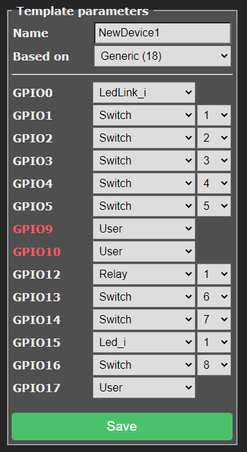
In most cases, all the remaining GPIO pins can be filled with a switchX to complete the next process in one step. Click Save and return to the Tasmota console log once the device reboots. On the console enter the command "so114 1" and press enter. This will decouple the switches from the relays and then pass the button number and action out to the console.
Toggle or hold down the button on the device. The console should show exactly which switch X was triggered by your button press. Super easy!

In this example, "Switch2" shows a TOGGLE, this is due to the press then depress of the button. If there are no additional buttons to find on the device, return to the configure template screen. Unassign all the switches, except for SwitchX you found and change it to Button 1. At this point, it is suggested to take a screenshot of your template configuration for backup purposes.
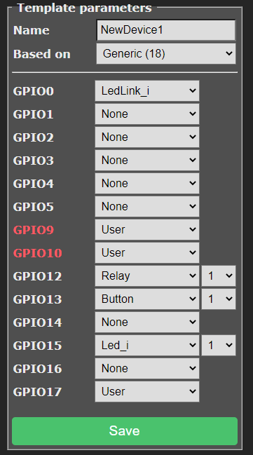
Last but not least, change the Template Name to a proper name, and issue a SetOption0 1 and SetOption114 0 command on the console to turn power state saves back on attach the switch/buttons to the relays. It is also recommended to use the Backup Configuration option in Tasmota.
Submit your findings to us on Discord or via this Site